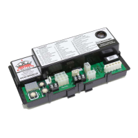
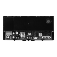
S9200U1000 UNIVERSAL HOT SURFACE IGNITION INTEGRATED FURNACE CONTROL
21 69-2075—01
3 + 5 Control failed Self Check, internal error, or
failed hardware (Control restarts if the error
recovers.)
This covers hardware errors like flame
sense circuit faults, pin shorts, etc.
Cycle power to appliance and run heating sequence. If this failure repeats, replace the
control.
3 + 6 Reversed Line Voltage Polarity or Poor
Earth Ground (Control restarts if the error
recovers within 5 minutes after the fault
has cleared.)
Check:
1. Line voltage input wiring. Assure line voltage hot lead is attached to
L1.
2. Ground wire from control to appliance and appliance earth ground.
3. Voltage between line volt Neutral and appliance chassis. If over 10 volts, repair the
wiring or move the furnace to another circuit with a good earth ground.
Repair: Reverse line voltage inputs if line volt hot lead is not attached to the L1 input.
Hard Lockout Codes
4 + 1 Hard Lockout - Rollout circuit open or
previously opened.
Check/Repair: Flue restrictions; heat exchanger restricted
Check burner. Check Rollout Switch including switch cables.
Reset rollout if necessary.
Do not operate until repairs are made.
Cycle power to appliance and run heating sequence.
If this failure repeats, replace the control.
4 + 2 Hard Lockout - Gas valve welded relay
detected for five times
Check/Repair: Gas valve wiring.
Cycle power to appliance and run heating sequence.
If this failure repeats, replace the control.
a
Flash Code Descriptions:
- Pulse: A 0.25 second flash followed by 3.75 seconds of off time.
- Heartbeat: Constant 0.5 second bright, 0.5 second dim cycles.
- During start-up the STATUS LED blinks fast for approximately 2 seconds. If the S9200U1000 continues blinking
fast (8 pulses/second), the control has failed and must be replaced.
- Standard LED Fault Pattern (Single X Flash): LED flashes X times at 2HZ, then off for 3 seconds.
- Advanced LED Fault Pattern (X + Y Flash): LED flashes X times at 2Hz, remains off for one second, flashes Y
times at 2Hz, remains off for three seconds, and then repeats.
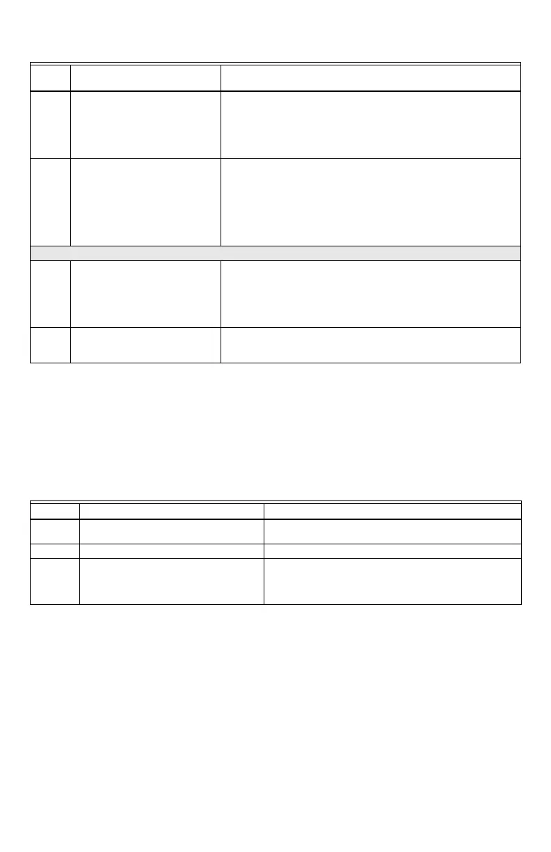
Table 11. Control Status Codes (Red LED). (Continued)
Flash
Code
a
Red LED Status Code and Error
Description Check / Repair
Table 12. E-COM Status Codes (Green LED).
Flash Code Green LED Status Code and Description
a
a
This LED is active even if a conventional thermostat is controlling the appliance.
Check / Repair
Rapid
Flashing
Bus Activity - Message being transmitted Not Applicable (normal operation)
Single Blink Bus Activity - Received message acknowledgment Not Applicable (normal operation)
Off No Bus Activity Check/Repair: Disconnect the S9200U1000 from the external bus wiring,
cycle power and check the bus activity. If there is activity, repair external
bus wiring/devices before reconnecting the S9200U1000 back.
If there is still no activity, replace the control.

 Loading...