S9200U1000 UNIVERSAL HOT SURFACE IGNITION INTEGRATED FURNACE CONTROL
7 69-2075—01
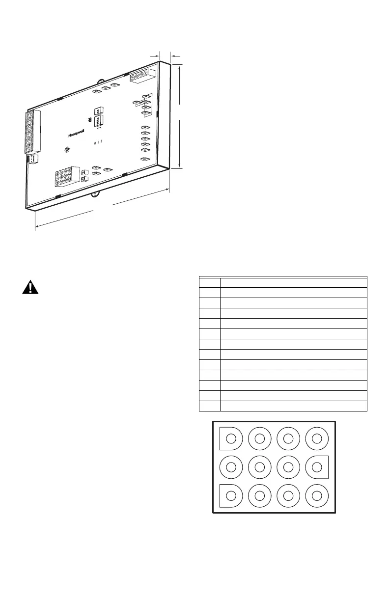
Fig. 1. S9200U1000 dimensions in inches and (mm).
Wiring
WARNING
Fire or Explosion Hazard.
Can cause severe injury, property damage, or
death.
Make sure the proper wiring harness is used.
Check the cross reference tables (Table 1 on
page 2) and review the appliance wiring
schematic.
The S9200U1000 is intended to connect to the appliance
with the aid of wiring harnesses. Carefully review the
wiring harness selection table for the correct wiring
harnesses. See Table 1 on page 2.
Check the wiring diagram (Fig. 4 on page 9) and the
diagram furnished by the appliance manufacturer for all
terminal designations. Table 4 and Table 5 beginning on
page 8 describe the wiring connections for Class 2 and
Class 1 installations.
Typical wiring connections are shown in Fig. 5 on
page 10.
Check the wiring diagrams furnished by the appliance
manufacturer, if available, for circuits that differ from the
general hookup shown. Carefully follow any special
instructions affecting the general procedures outlined
below.
All wiring must comply with local codes and ordinances.
See “Wiring Harnesses” on page 7 for the main and
igniter/inducer harness plug connections and details.
See “Wiring Connections” on page 8 for wiring
connections, but also refer to furnace manufacturer
instructions, if available.
NOTE: The Safety Timing jumper is described in Table 6
on page 11.
IMPORTANT
The common ground required for the
S9200U1000 and the main burner must be sup-
plied through the plug connected to the Main
Harness (12-pin connector) receptacle on the
board.
Wiring Harnesses
The following describes the main and igniter/inducer
harness connections.
MAIN HARNESS PLUG CONNECTIONS
The following describes the harness plug connectors for
the main harness. See Table 2 and Fig. 2.
IMPORTANT
The common ground required for the
S9200U1000 and the main burner must be sup-
plied through the plug connected to the Main
Harness (12-pin connector) receptacle on the
board.
.
Fig. 2. S9200U1000 Main harness plug configuration.
4 1/8
(105)
1 1/2
(38)
6 1/8
(156)
M24905
Table 2. Main Harness Plug Connector 12-pin
(Class 2, Low Voltage).
Pin # Function
1High Limit Out
2 Flame Sense - Flame Signal Input (90 Vac, current limited)
324 Vac Hot
4 Not Used
5 Rollout Switch Out
624 Vac Common
7 High Limit In + Pressure Switch Out
8 Chassis Ground
9 Main Valve Common
10 Pressure Switch In
11 Rollout Switch In
12 Main Valve
1 4 7 10
2 5 8 11
3 6 9 12
M24906

 Loading...