S9360, S9361, S9370, S9371 INTEGRATED BOILER CONTROLLERS
69-2076—03 8
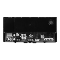
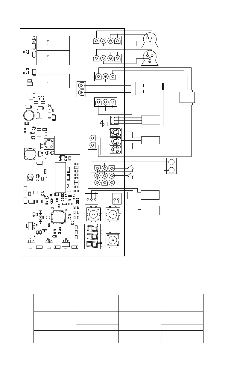
Fig. 5. Hot Surface Ignition (HSI) Wiring (S937X).
Common Connectors
SENSOR 1
SENSOR 2
GAS
CONTROL
MV
MV
PRESSURE SWITCH
LIMIT SWITCH
M24218
ENVIRACOM
DISPLAY
ENVIRACOM
DIAGNOSTIC
24 VAC
TRANSFORMER
L2
L1
GND
FLAME
SENSE
HOT SURFACE
IGNITER
CIRCULATOR
INDUCER
GND
Table 3. Connectors Common to Both Spark-to-Pilot and HSI Options.
Connection/Color Pin Mating Plug Description
Flame Sense 1 of 1 3/16 in. female quick-
connect
Connection to Flame
Rod
Sensor 1/White 1 of 3
Molex
®
43061-0003
NTC 1-1
2 of 3 Sensor Common
3 of 3 NTC 1-2
Sensor 2
a
/White
1 of 2
Molex
®
43061-0002
NTC Temperature
Sensor
2 of 2
 Loading...