Sensepoint XCD RFD Technical Manual SPXCDHMRFENU Issue 1
7
4.1 Transmitter
The transmitter enclosure has three threaded entries. The two cable entries either side
of the upper part of the transmitter housing are for connecting the power source, signal
output and relay contacts to associated signalling equipment. The bottom entry allows
local (direct) mounting of the appropriate sensor. These three entries are ¾” NPT for the
Americas.
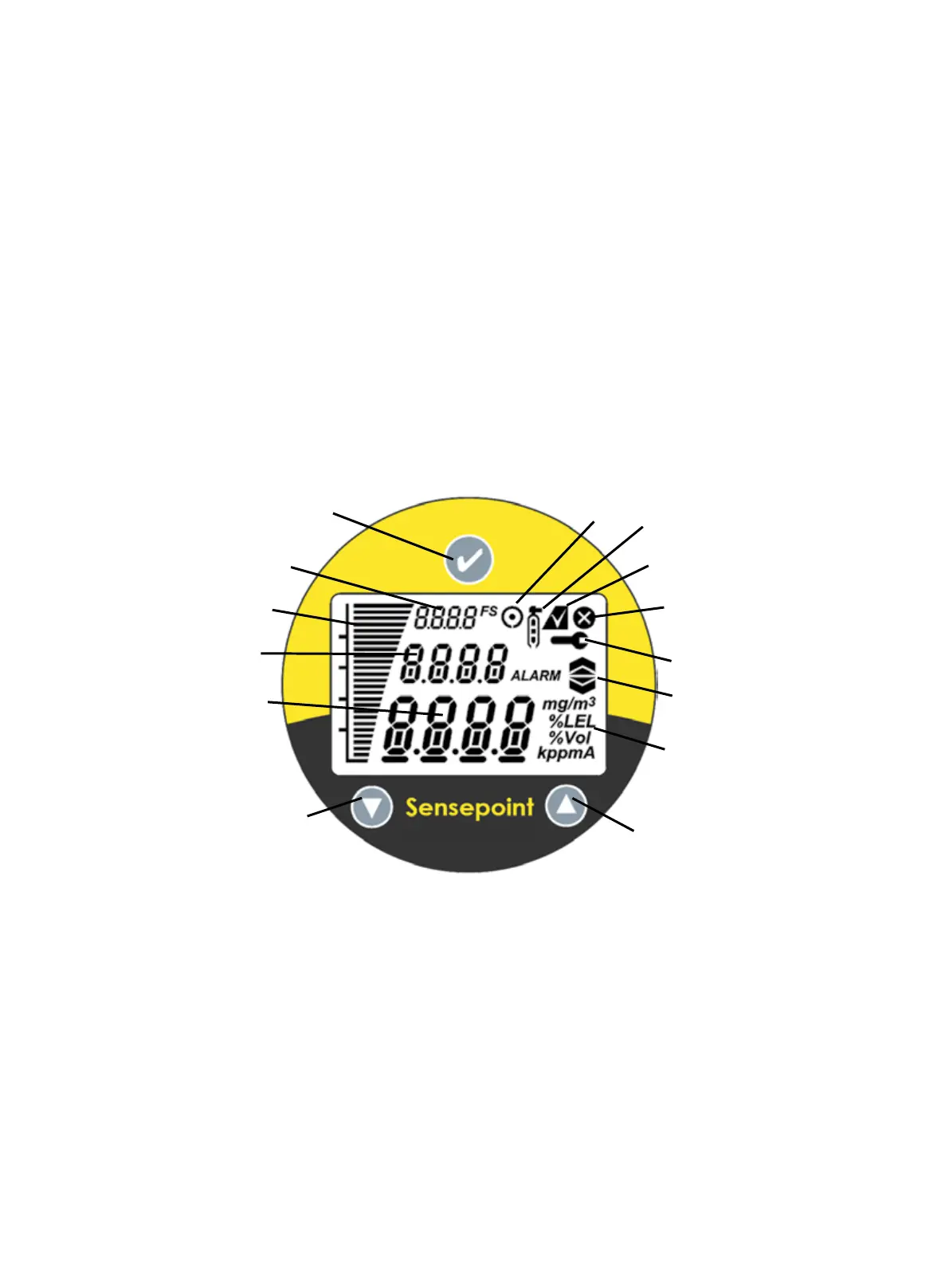
A local LCD provides gas type, concentration, alarm and operating status. The display
provides numerical, bar graph and icon information.
Diagnostic information may also be displayed when the transmitter is interrogated using
a magnet. The transmitter cover has a glass window which allows use of the Magnetic
Wand to activate the three user interface magnetic switches that are located on the front
of the display module. The magnet also enables a non intrusive, one-man calibration and
conguration facility for the Sensepoint XCD RFD.
4.2 Flammable Gas sensors
The Sensepoint XCD/RFD Transmitter is designed to work with the following ammable
gas sensor types described in below sections 4.2.1, 4.2.2 and 4.2.3. Sensepoint XCD
sensors use electro-catalytic technologies. The Sensepoint XCD RFD is cCSAus approved
for use in North America.
Please refer to chapter 15 ‘Ordering information’ for more detail information.
Diagram 2: Sensepoint XCD RFD Display and Magnetic Switches
Measuring
Units
Inhibit Icon
Test Pass Icon
Warning
Fault Icon
Magnetic Wand
activation Icon
Gas Type
Magnetic
MENU/ENTER
Switch
Magnetic
UP Switch
Magnetic
DOWN
Switch
Gas Reading
Bar Graph
Alarm Icon
Full Scale
Calibration Icon
XCD RFD

 Loading...