Calibration Handbook
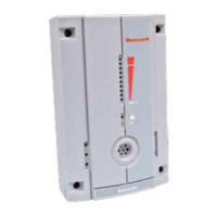
123Sensepoint XCD
Sensepoint XCD Calibration
It is recommended to periodically carry out a gas response check on the Sensepoint XCD to ensure correct
operation. This may be done in two ways;
1. A simple Response Check often referred to as a “BUMP TEST” is a test using calibration gas applied
to
the sensor via the nozzle of the
Weather Protection or using the Sensepoint XCD Gassing Cap.
If a BUMP TEST is done via the Weather Protection nozzle it may be necessary in windy conditions
to
increase
the flow rate of the test gas by a further 1 LPM, OR, to shelter the weather protection from
the
wind.
2.
A full gas calibration of the sensor as described in the following section, using ONLY the Sensepoint
XCD
Gassing Cap (P
art No.: S3KCAL).
Zero and Span
CAUTION
Before initial calibration allow the detector to stabilize for 30 minutes after applying power.
When in zeroing and span calibration mode the current output from the detector is inhibited (default 2mA) to
avoid false alarms.
For Flammable gas calibration use a calibration gas concentration of between 25%LEL and 75%LEL to ensure
that the required accuracy can be attained.
!"# $%&"!'()# *+,-&(# .%/(# 0()0!"0# "(1("# .!# 0(2.3!)# 456467# 8(1!"(# 2!)&+2.3)'# 9("!# :)&# 0/:)# 2:,38":.3!)6
To calibrate the detector, use an appropriate span gas cylinder, constant flow regulator AND the Sensepoint
XCD Gassing Cap. The flow rates used for calibration gas are as follows:
Gas Type Flow rate (L / Min)
Air or N2 for Zero 0.5 to 1.0
Flammable CAT 1 to 1.5
O2 0.5 to 1.0
H2S 0.5 to 1.0
CO 0.5 to 1.0
H2 0.5 to 1.0
NO2 0.5 to 1.0
Flammable IR 0.4 to 0.6
CO2 IR 0.4 to 0.6
A compressed air cylinder (20.9%Vol oxygen) should be used to perform the zero calibration if the area where
the detector is located contains any residual amount of the target gas. If no residual gas is present then the
background air can be used to perform the zero calibration. Contact your Honeywell Analytics representative
for details of suitable calibration kits.
To calibrate the detector follow the procedure below.
NOTE
!"#$%&'$%'()&*($'&%(+&)$,-.)$&/&0$)(.%#&1)(2$*-)$3&4/25#)(-%*&/.)&67839:;(<&(!"#$%=&2/%&>$&-'$*&+(&
'1/%&+?$&(!"#$%&'$%'()&.%&1</2$&(@&/&2(A1)$''$*&/.)&2"<.%*$)&67839:;(<&(!"#$%=3&B()&(!"#$%&'$%'()'&(%<"&
*(&1/)+'&CDEF&C7F&CG&6.@&2(A1)$''$*&/.)&2"<.%*$)&.'&-'$*=F&CEDCH&/%*&77&(@&+?$&1)(2$*-)$&>$<(I3

 Loading...