7. Equivalent Isotropically Radiated Power (EIRP)
7.1. EIRP LIMITS
Revision 1 SmartLine Wireless Transmitter Professional Installation Guide 17
Notes for Table 7-2
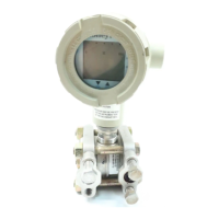
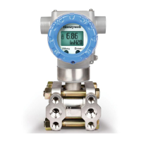
1. The Model Number of any instrument may be found on the identification name plate located on
the outside of the SmartLine Wireless transmitter. The values in the Cable(s) Length column
represent those customer selections from Table IV of the SmartLine Wireless Model Selection
Guides.
2. In the Cable(s) Length column, entries of the form “X+X” indicate that there are two cables
between the SmartLine Wireless and the remote antenna, with a lightning surge arrestor used to
connect the two cables together. Entries of the form “X” mean that there is a single cable and
that no lightning surge arrestor is used. For entries of the form “X+X”; the first value is the
length of the cable between the instrument and the arrestor while the second value is the length of
the cable between the arrestor and the remote antenna. All cables are 400 series types as
specified in Section 5 and Table 5-1.
3. TX Power is set by the Honeywell factory producing the SmartLine Wireless. The factory set
value for TX power is determined by the customer’s model number selections in the Model
Selection Guide Table III for antenna type, cables and the lightning suppressor along with the
customer’s selection in Table V for Country Code and is consistent with the values shown in
Table 7-2. If the Country location, cable lengths, antenna type or the use of a lightning surge
arrestor are changed in the field away from the Model Number listed on the instrument’s
nameplate, then the TX power setting should likewise be changed per the tables above to match
the new Country/antenna/cable/arrestor selections.
See Section 8.
4. Note reserved for future Japan certification
5. The TX Power Setting values given in Table 7-2 represent the power produced by the Radio
circuit within the RF Module. These TX Power Setting values do not include antenna gain nor
do they include the losses caused by cables, connectors and lightning arrestors. When these
external gains and losses are included, then using the TX power values in Table 7-2 ensures that
the SmartLine Wireless EIRP will not exceed the maximum EIRP limits that are given in Table
7-1
6. The TX Power Setting values given in Table 7-2 for the 14 dBi directional antenna are also used
for the 14 dBi sectional antenna shown in Table 6-1. This sectional antenna is only approved for
use in Japan.
7. Units with Model Selection Guide Table IV selection ---A00 are shipped without cables or a
remote antenna. The Professional Installer must set the TX power for these units according to
the characteristics of the antenna and cables selected by the end user, guided by the information
provided above. Only Omnidirectional antennas with gains less than or equal to 8 dBi and
Directional antennas with gains equal to or less than 14 dBi may be used and still meet Agency
restrictions. The TX values used must result in an EIRP value that does not exceed the
maximum EIRP values given in Table 7-1. Honeywell recommends that, regardless of the
antenna and cables used, that TX power not be set higher than 16 dBm in order to maximize the
battery life of the instrument.
8. Note reserved for future use