EasyManuals Logo

Honeywell T6 Pro Installation Guide

Honeywell T6 Pro
33 pages
To Next Page IconTo Next Page
To Previous Page IconTo Previous Page
Page #7 background imageLoading...
Page #7 background image
transformer.
Wiring
NOTES:
1. Available wiring configurations differ by product models/product numbers.
2. Use 18- to 22- gauge thermostat wire. Shielded cable is not required.
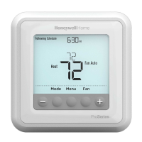
3. Set the R Slider Tab on the UWP to the up position (1 wire) for 1 transformer systems or the down position (2
wires) for 2 transformer systems. See “Setting Slider Tabs” on page 4.
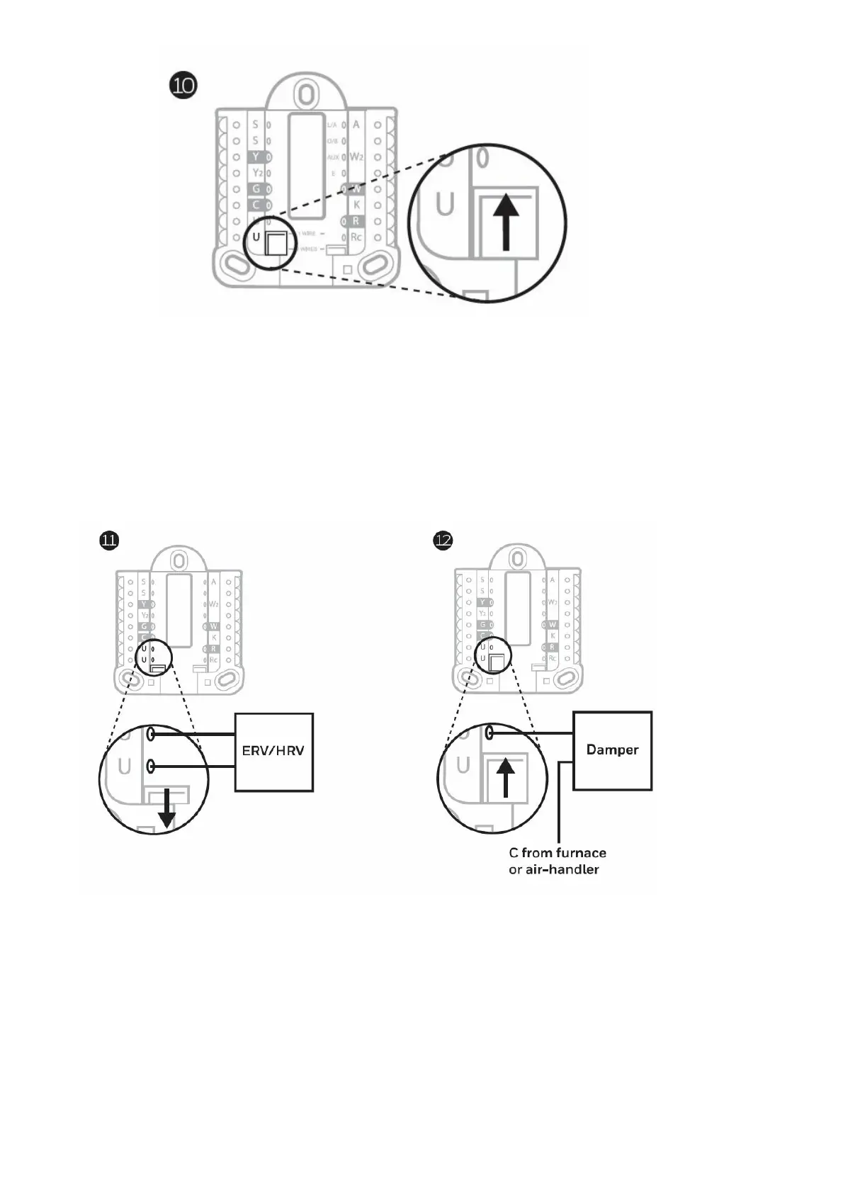
4. Set the U Slider Tab to the up position (1 wire) for non-powered ventilation or the down position (2 wires) for
powered ventilation. See “Setting Slider Tabs” on page.
Conventional systems
1H/1C System (1 transformer)
R Power
Rc [R+Rc joined by Slider Tab]
Y Compressor contactor
C 24VAC common
W Heat relay
G Fan relay
1H/1C System (2 transformers)
R Power (heating transformer)
Rc Power (cooling transformer)

Other manuals for Honeywell T6 Pro

Questions and Answers:

Question and Answer IconNeed help?

Do you have a question about the Honeywell T6 Pro and is the answer not in the manual?

Honeywell T6 Pro Specifications

General IconGeneral
DisplayTouchscreen
Energy Star CertifiedYes
Power SourceBattery or Hardwired
Operating ModesHeat, Cool, Auto, Off
GeofencingYes
CompatibilityWorks with most HVAC systems
Fan ModesAuto, On, Circulate
Remote AccessYes
Energy Saving FeaturesSmart Response Technology
ConnectivityWi-Fi
Warranty5-year limited warranty

Related product manuals