63-4038—7 6
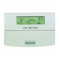
Fig. 8—Five T7047G1000 Sensors providing a
temperature averaging network for a T7300/
Q7300 Thermostat/Subbase.
T7200/T7300/Q7300
INSTALLATION
New Installation
Run cable to a hole at the selected wall location for the
thermostat and pull about 3 in. (76 mm) of wire through the
opening. Color-coded, 18-gauge thermostat cable with at
least one conductor for each wiring terminal is recom-
mended. Good service practice recommends selecting a
cable with one or two extra conductors than the immediate
application requires.
If using remote temperature sensor(s) or LAN override
switch module, refer to the mounting instructions included
with the device for wiring cable requirements. Route cable
away from sources of electrical noise.
IMPORTANT: The remote sensor(s) or override switch
wires must be in a shielded cable if bundled or placed
in the same conduit with the cooling control wires.
Earth ground the shield at the thermostat.
SET Q7300 SUBBASE DIP SWITCHES
NOTE: Subbase dip switches are not available on the T7200
Wallplate.
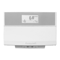
The Q7300 Subbase provides the T7300 Thermostat
with an interface to the single zone HVAC system. See
Table 5 for DIP switch settings. The subbase DIP switches
are located on the front and to the right of the wiring
terminals. See Fig. 10. Set the DIP switches for the system
being controlled.
TABLE 5—SUBBASE DIP SWITCH SETTINGS.
M3422
TT
Q7300
T
T
T7047G
T
T
T7047G
T
T
T7047G
T
T
T7047G
T
T
T7047G
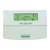
Fig. 9—Nine T7047C1025 Sensors providing a
temperature averaging network for a T7300/
Q7300 Thermostat/Subbase.
M3419
TT
TT
Q7300
T7047C
TT
T7047C
TT
T7047C
TT
T7047C
TT
T7047C
TT
T7047C
TT
T7047C
TT
T7047C
TT
T7047C
Switch Setting Function
1
a
OFF 1 stage heat
ON
b
2 stage heat
2
a
OFF 1 stage cool
ON
b
2 stage cool
3 OFF Proportional control (allows droop)
ON
b
Proportional plus integral (P+I)
control (droopless)
4
c
ON
b
Energizes fan on cool only
OFF Energizes fan on heat and cool
5ON
b
Use internal sensor
OFF Use remote sensor
a
No effect on 1 heat/1 cool (Q7300A) or 1 heat/3 cool
(Q7300G) models.
b
Factory setting.
c
No effect on heat pump systems.
MOUNT SUBBASE OR WALLPLATE
The subbase or wallplate can be mounted on a horizon-
tal outlet box or directly on the wall. For an outlet box
installation, go to step 3.
 Loading...