69-1434–1
3
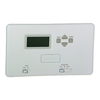
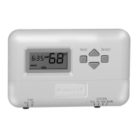
T8000C PROGRAMMABLE THERMOSTAT
KEEP WIRING IN
SHADED AREA
MOUNTING
SCREW HOLE
MOUNTING
SCREW HOLE
WIRING ENTRANCE
HOLE
M12560
G
R
Rc
Y
W
B
O
Fig. 4. Restrict wiring to shaded area.
The T8000C Thermostat is powered through the heating/
cooling system controls and is adaptable to most 18 to 30
Vac heating-cooling systems. Refer to Fig. 5, 6, and 7 for
typical wiring hookups.
Fig. 5. Typical hookup of T8000C in heat-cool system
with single transformer.
Fig. 6. Typical hookup of T8000C in heat-cool system
with two transformers.
L1
(HOT)
L2
M12561
FAN
RELAY
COMPRESSOR
CONTACTOR
TRANSFORMER
COOL
DAMPER
1
POWER SUPPLY. PROVIDE DISCONNECT MEANS AND OVERLOAD
PROTECTION AS REQUIRED.
CAN BE USED FOR CHANGEOVER VALVE ON SINGLE-STAGE HEAT
PUMP SYSTEMS.
JUMPER R TO Rc.
2
2
2
1
Y
G
Rc
W
3
R
B
O
HEAT
RELAY
HEAT
DAMPER
Y
G
Rc
W
2 4
R
B
O
M12562
L1
(HOT
L2
FAN
RELAY
HEAT
RELAY
L1
(HOT)
L2
COMPRESSOR
CONTACTOR
HEATING
TRANSFORMER
COOLING
TRANSFORMER
HEAT
DAMPER
COOL
DAMPER
1
POWER SUPPLY. PROVIDE DISCONNECT MEANS AND OVERLOAD
PROTECTION AS REQUIRED.
REMOVE JUMPER RC TO R WHEN INSTALLED ON A TWO TRANSFORMER
SYSTEM.
CAN BE USED FOR CHANGEOVER VALVE ON SINGLE-STAGE HEAT
PUMP SYSTEMS.
POWER TO R TERMINAL IS REQUIRED WHEN THE SYSTEM SWITCH IS IN
THE OFF POSITION.
2
3
3
1
1
3
4
 Loading...