69-1434–1
4
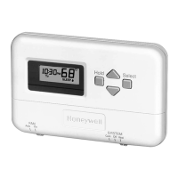
T8000C PROGRAMMABLE THERMOSTAT
Fig. 7. Typical wiring diagram for T8000C on zone 1
MABS II/L control panel.
Setting Fan Operation (Fuel) Switch
The fan operation (fuel) switch is preset at the factory in
the F position. See Fig. 8. This is the correct setting for
most systems. If this system is an electric heat system, set
the switch to the E position. The E setting allows the fan to
turn on immediately with the heating or cooling equipment
in a system where the G terminal is connected.
T8
T7
T6
T5
O1
G1
B1
E1
T4
ZONE
CHANGEOVER
CONTROL
Y
G
Rc
W
1
1 JUMPER R TO RC.
R
B
O
T8000C THERMOSTAT
M1258
0
FAN OPERATION (FUEL) SWITCH
F
E
Fig. 8. Fan operation (fuel) switch.
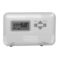
Mounting Thermostat to Wallplate
1. Slide SYSTEM switch to the Off position.
2. Engage the tabs at the top of the thermostat and
wallplate.
3. Swing down the thermostat and press the lower
edge of the thermostat onto the wallplate to latch.
See Fig. 9.
Fig. 9. Mounting thermostat to wallplate.
Installer Setup
Setting °F/°C Indication and Heat Cycle Rate
The following instructions provide the information neces-
sary to change the heating cycle rate to match the heating
equipment and to choose either Fahrenheit (°F) or Celsius
(°C) display.
NOTE: All four steps must be completed to save
changes to the °F/°C indication and the heat
cycle rate.
M1467
DASHED LINES INDICATE TABS
ON BACK OF THERMOSTAT
ENGAGE TABS AT TOP OF THERMOSTAT
WITH SLOTS ON WALLPLATE.
PRESS LOWER EDGE OF
CASE TO LATCH.
A
B
SYSTEM
Cool Off Heat
Auto On
FAN
Hold
Select
SYSTEM
Cool Off Heat
Auto On
FAN
Hold
Select
T
U
E
P
M

 Loading...