69-1432-1
2
T8000, T8001 PROGRAMMABLE THERMOSTAT
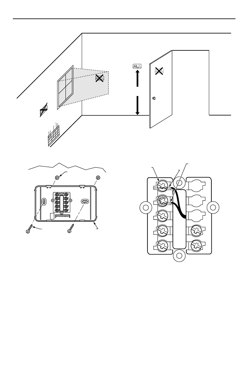
Fig. 1. Typical location of thermostat.
5 FEET
[1.5 METERS]
YES
NO
NO
NO
M11338
M12202
WALL
WALL
ANCHORS (2)
WALLPLATE
MOUNTING
SCREWS (2)
Fig. 2. Mounting wallplate to wall.
Wiring
IMPORTANT
Use an 18-gauge maximum wire for wiring the
thermostat.
All wiring must comply with local electrical codes and
ordinances. Disconnect the power supply to prevent
electrical shock or equipment damage.
The shape of the terminals permits insertion of straight or
wraparound wiring connections; either method is accept-
able. A letter code is located near each terminal for
identification. See Fig. 3.
NOTE: To ensure proper mounting of thermostat, restrict
all wiring to the shaded area in the center of the
terminals. See Fig. 4.
CREW
G
R
C
Y
W
B
O
INSERTION STRIP
5/16 IN. (8 MM)
STRIP 7/16 IN. (11 MM
Fig. 3. Wiring connections.
 Loading...