69-1432-1
4
T8000, T8001 PROGRAMMABLE THERMOSTAT
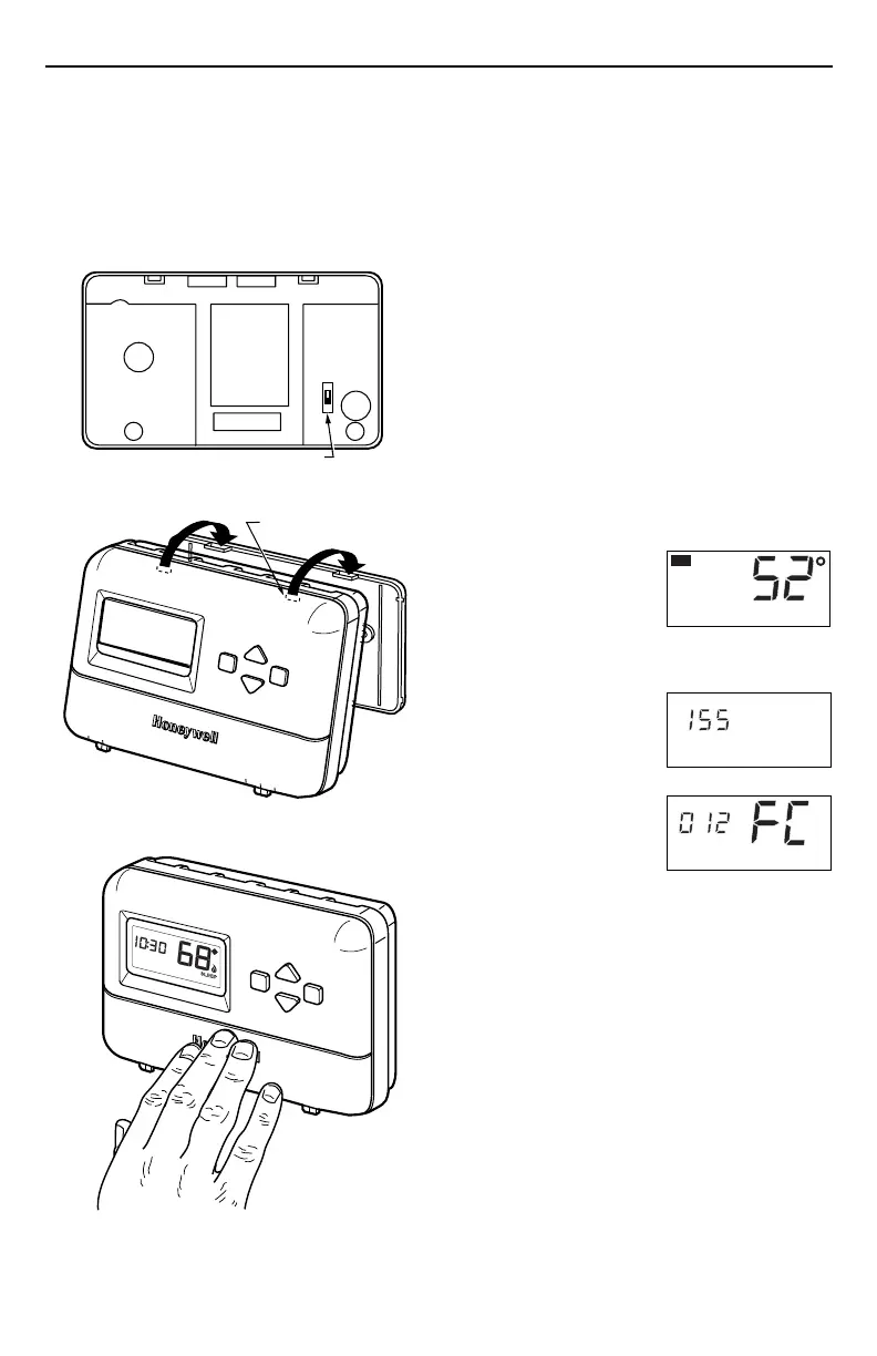
Fig. 9. Mounting thermostat to wallplate.
Mounting Thermostat to Wallplate
1. Slide SYSTEM switch to the Off position.
2. Engage the tabs at the top of the thermostat and
wallplate.
3. Swing down the thermostat and press the lower
edge of the thermostat onto the wallplate to latch.
See Fig. 9.
INSTALLER SETUP
Setting °F/°C Indication and
Heat Cycle Rate
The following instructions provide the information neces-
sary to change the heating cycle rate to match the heating
equipment and to choose either Fahrenheit (°F) or Celsius
(°C) display.
NOTE: All four steps must be completed to save
changes to the °F/°C indication and the heat
cycle rate.
1. Enter Installer Setup.
a. Use ▲ or ▼ keys
to set the tempera-
ture setpoint to
52°F (11°C).
b. Press the ▲ and ▼ keys simultaneously for
more than two seconds to enter installer
setup.
c. When released,
the three-digit
software revision
code is displayed.
d. Press the ▲ key.
Factory
configuration
(FC) is displayed
(A typical
example is
shown, but
information displayed varies by
model. This information is for factory use
only).
Optional System Checkout
When in steps 1c and 1d only, pressing the ▼ key can be
used to turn heat or cool outputs on and off. Change the
SYSTEM switch setting to test heat or cool outputs. No
action takes place If the system switch is in the Off
position.
Examples: System setting at HEAT: If heat is on,
pressing the ▼ key turns it off; if heat is off,
pressing the ▼ key turns it on.
System setting at COOL: If cool is on,
pressing the ▼ key turns it off; if cool is off,
pressing the ▼ key turns it on. The 5 minute
minimum off time is bypassed.
M12582
SET
HT.
M12583
M12584
M1467
DASHED LINES INDICATE TABS
ON BACK OF THERMOSTAT
ENGAGE TABS AT TOP OF THERMOSTAT
WITH SLOTS ON WALLPLATE.
PRESS LOWER EDGE OF
CASE TO LATCH.
A
B
SYSTEM
Cool Off Heat
Auto On
FAN
Hold
Select
SYSTEM
Cool Off Heat
Auto On
FAN
Hold
Select
TUE
PM
M1258
0
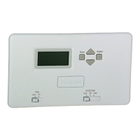
FAN OPERATION (FUEL) SWITCH
F
E
Setting Fan Operation (Fuel) Switch
The fan operation (fuel) switch is preset at the factory in
the F position. See Fig. 9. This is the correct setting for
most systems. If this system is an electric heat system, set
the switch to the E position. The E setting allows the fan to
turn on immediately with the heating or cooling equipment
in a system where the G terminal is connected.
Fig. 8. Fan operation (fuel) switch.
 Loading...