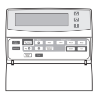
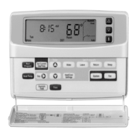
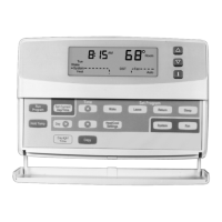
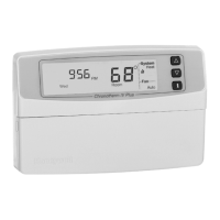
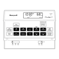
T8611G CHRONOTHERM
®
IV DELUXE PROGRAMMABLE HEAT PUMP THERMOSTAT
68-0165—1
5
Standard
Terminal
Designations
Alternate
Terminal
Designations Typical Connection Function Terminal Type
B— Heating changeover valve Output 24V powered contact
CB
a
, C, X1, X2 Common Input
EK Emergency heat relay Output 24V powered contact
GF Fan relay Output 24V powered contact
L A, A1, C, L, X, Z User defined Light Emitting Diodes (LEDs) Annunciation —
OR Cooling changeover valve Output 24V powered contact
O/B — Cooling or heating changeover valve
(configure in Installer Setup 29)
Output 24V powered contact
OT, OT — Outdoor temperature sensor (C7089B) Input —
P— Defrost Output 24V powered contact
RV 24V system or heating transformer Input —
RC — 24V cooling transformer Input —
W1 H1, R3 Stage 1 heating relay Output 24V powered contact
W2 H2, R4, W3, Y Stage 2 heating relay or auxiliary heat relay Output 24V powered contact
X1, X2, X3, X4 A, A1, A2, C, L,
X, Z
User defined Light Emitting Diodes (LEDs) Annunciation —
Y, Y1 C1, M, Y Stage 1 compressor contactor Output 24V powered contact
a
Some OEM models label the terminal for transformer common B.
Table 4. Terminal Designations and Descriptions.
CAUTION
Disconnect power before wiring to prevent electrical
shock or equipment damage.
1. Loosen the terminal screws on the wallplate and
connect the system wires. See Fig. 4
IMPORTANT
Use 18 gauge, color-coded thermostat cable for
proper wiring.
2. Securely tighten each terminal screw.
3. Push excess wire back into the hole.
4. Plug the hole with nonflammable insulation to prevent
drafts from affecting the thermostat.
M4826
FOR WRAPAROUND
INSERTION STRIP
7/16 IN. (11 MM).
FOR STRAIGHT
INSERTION STRIP
5/16 IN. (8 MM).
Fig. 4. Proper wiring technique.
 Loading...