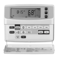
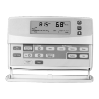
T8611G CHRONOTHERM
®
IV DELUXE PROGRAMMABLE HEAT PUMP THERMOSTAT
68-0165—1
4
Fig. 2. Typical location of thermostat.
Wallplate Installation
The thermostat can be mounted horizontally on the wall or on
a 2 in. x 4 in. wiring box. Position wallplate horizontally on the
wall or on a 2 in. x 4 in. wiring box.
1. Position and level the wallplate (for appearance only).
The thermostat will function properly even when not
level.
2. Use a pencil to mark the mounting holes. See Fig. 3.
WIRES
THROUGH WALL
WALL
MOUNTING
HOLES
M10822
MOUNTING
SCREWS
WALL
ANCHORS
(2)
5 FEET
[1.5 METERS]
YES
NO
NO
NO
M10106
Fig. 3. Mounting the wallplate.
3. Remove the wallplate from the wall and drill two 3/16
inch holes in the wall (if drywall) as marked. For firmer
material such as plaster, drill two 7/32 inch holes.
Gently tap anchors (provided) into the drilled holes until
flush with the wall.
4. Position the wallplate over the holes, pulling wires
through the wiring opening.
5. Loosely insert the mounting screws into the holes.
6. Tighten mounting screws.
WIRING
All wiring must comply with local electrical codes and
ordinances. Follow equipment manufacturer wiring
instructions when available. Refer to Fig. 15 and 16 for typical
hookups. A letter code is located near each terminal for
identification. Refer to Table 4 for terminal designations.
 Loading...