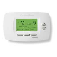
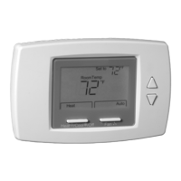
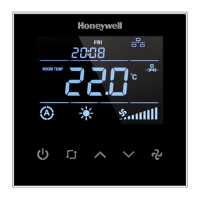
TB3 SERIES COMMUNICATING THERMOSTATS INSTALLATION INSTRUCTIONS
31-00576-01 12
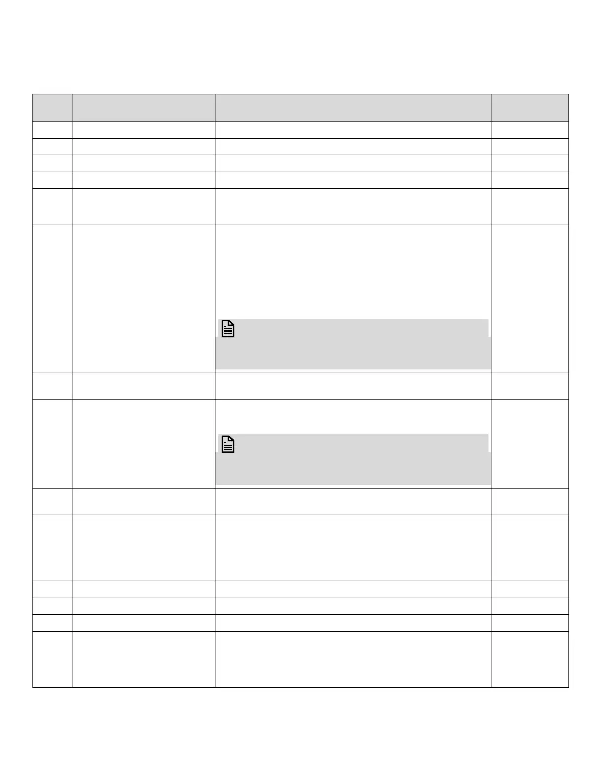
CONFIGURATION MENU PARAMETERS
NO NAME OF PARAMETER PARAMETER DEFINITION
FACTORY
DEFAULT
P1 Hardware Version Device hardware version 2.1
P2 Firmware Version Device firmware version 2.7
P3 Setpoint High Limit Range: 5°C to 40 °C (41 °F to 104 °F) 30 °C (86 °F)
P4 Setpoint Low Limit Range: 5°C to 40 °C (41 °F to 104 °F) 5 °C (41 °F)
P5 Main Screen
0 = Room temperature
1 = Setpoint temperature
2 = Swap room temperature and setpoint temperature
0
P6 Key Lock
0 = Unlocked
1 = Lock On/Off
2 = Lock mode
4 = Lock setpoint
8 = Lock fan speed
16 = Lock time settings
32 = Lock time schedule settings
63 = Locked all
NOTE:
To lock two or more buttons at the same time, add
the button values. Enter 12 to lock the setpoint (4)
and fan speed (8).
0
P7 Celsius or Fahrenheit
0 = Celsius
1 = Fahrenheit
0
P8 Time Format
0 = 24 hours clock
1 = 12 hours clock (AM/PM)
NOTE:
The system time is displayed using a 24-hour clock.
This parameter changes how the clock format will
appear on the panel or screen.
1
P9 Time Schedule Enable
0 = Disable
1 = Enable
0
P10 Screen Saver
0 = Screen saver disabled
1 = Display On
2 = Display Off
3 = Only room temperature
4 = Room temperature and clock
5 = Swap room temperature and setpoint with clock
4
P11 Screen Saver Mode Delay Range: 10 to 150 seconds 60 seconds
P12 LCD Brightness Range: 1 to 5 stage 5
P13 Buzzer Stage Range: 0 to 5 stage 3
P14 Power Failure
This parameter adjusts the device's condition to continue
when the power fails.
0 = Device starts off
1 = Device starts on
2 = Keep State Before Power Failure
2
 Loading...