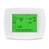
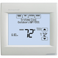
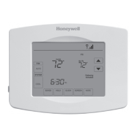
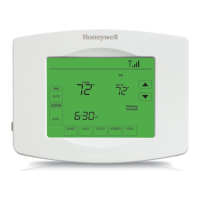
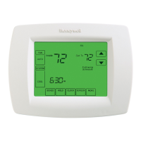
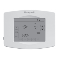
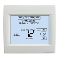
VISIONPRO® 8000 SMART THERMOSTAT
21 33-00096—04
316 Backup Heat Cycles
Per Hour Stage 1
Note: “Stage 1" is
not displayed if
there is only 1
stage.
1 to 12 CPH
Electric =
9 CPH
Gas / Oil =
5 CPH
Both This ISU is only displayed when ISU 207 or 213
Backup Heat Stages is set to 1 stage.
Cycle rate limits the maximum number of times the
system can cycle in a 1 hour period measured at a
50% load. For example, when set to 3 CPH, at a
50% load, the most the system will cycle is 3 times
per hour (10 minutes on, 10 minutes off). The
system cycles less often when load conditions are
less than or greater than a 50% load. The
recommended cycle rate settings are below for each
heating equipment type:
Standard Efficiency Gas Forced Air = 5 CPH
High Efficiency Gas Forced Air = 3 CPH
Oil Forced Air = 5 CPH
Electric Forced Air = 9 CPH
Hot Water Fan Coil = 3 CPH
Hot Water Radiant Heat = 3 CPH
Geothermal Radiant Heat = 3 CPH
Steam = 1 CPH
Gravity = 1 CPH
316 Backup Heat Cycles
Per Hour Stage 2
1 to 12 CPH
Electric =
9 CPH
Gas / Oil =
5 CPH
Both This ISU is only displayed when ISU 207 or 213
Backup Heat Stages is set to 2 stages.
Cycle rate limits the maximum number of times the
system can cycle in a 1 hour period measured at a
50% load. For example, when set to 3 CPH, at a
50% load, the most the system will cycle is 3 times
per hour (10 minutes on, 10 minutes off). The
system cycles less often when load conditions are
less than or greater than a 50% load. The
recommended cycle rate settings are below for each
heating equipment type:
Standard Efficiency Gas Forced Air = 5 CPH
High Efficiency Gas Forced Air = 3 CPH
Oil Forced Air = 5 CPH
Electric Forced Air = 9 CPH
Hot Water Fan Coil = 3 CPH
Hot Water Radiant Heat = 3 CPH
Geothermal Radiant Heat = 3 CPH
Steam = 1 CPH
Gravity = 1 CPH
324 Compressor Off
Time
Off
1 - 5 minutes
5 minutes Both The thermostat has a built in compressor protection
(minimum off timer) that prevents the compressor
from restarting too early after a shutdown. The
minimum-off timer is activated after the compressor
turns off.
If there is a call during the minimum-off timer, the
thermostat shows “Wait” in the display.
326 Extended Fan Run
Time in Cool
0, 30, 60, 90 seconds, 2, 3, 4, 5,
6, 7, 8, 9, 10, 11, 12, 13, 14, 15
minutes
0 seconds Both After the call for cooling ends, the thermostat keeps
the fan on for the selected amount of time for
increased efficiency. This may re-introduce humidity
into the living space.
326 Extended Fan Run
Time in Heat
0, 30, 60, 90 seconds, 2, 3, 4, 5,
6, 7, 8, 9, 10, 11, 12, 13, 14, 15
minutes
0 seconds Both After the call for heating ends, the thermostat keeps
the fan on for the selected amount of time for
increased efficiency.
Table 2. Installer Setup (ISU) Table. (Continued)
ISU
Number
Installer Setup
Name Settings Default
Residential,
Commercial
or Both Notes
 Loading...
