TZ-3 TOTALZONE® ZONE CONTROL PANEL
68-0223-2 6
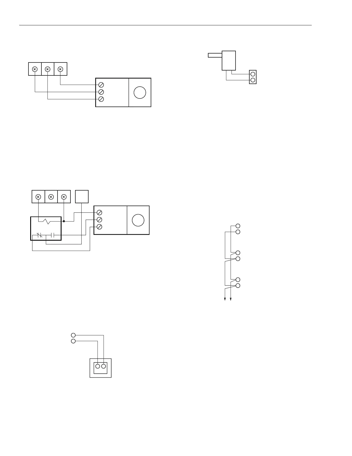
Fig. 9. MARD and CDO-51 Damper wiring.
When the ML6161 Motor Actuator is used, wire as shown in
Fi
. 10. Wire the R8222 rela
to
revent the dam
er LED from
constantl
li
htin
amber.
Fig. 10. ML6161 Damper Motor Actuator wiring.
Wire the transformer to the
anel as shown in Fi
. 11.
NOTE: If the installation includes an Add-A-Zone
anel, see
the TotalZone Add-A-Zone Panels section.
Fig. 11. Transformer wiring.
Discharge Air Temperature Sensor
Wire the C7735A or the ZMS to the
anel as shown in Fi
. 12.
Fig. 12. Discharge Air Temperature Sensor (C7735A or
ZMS) wiring.
Wire the Add-A-Zone
TAZ
Panel to the TotalZone
TZ-3
Panel as shown in Fi
. 13. U
to nine TAZ Panels can be
wired to one TZ-3
anel. See Fi
. 13.
Use 18-
au
e thermostat wire for runs u
to a maximum of
500 feet. Kee
these wires at least 12 in. from line volta
e
wirin
and e
ui
ment; otherwise, use shielded cable wirin
.
IMPORTANT:
When multiple panels are used, it is important that
the transformers be in-phase. Check the phasing by
measuring for 24V across the TR2 transformer termi-
nals on each panel. There should be 0 Vac. If not,
reverse the TR1and TR2 transformer wires on one of
the panels and recheck.
Fig. 13. TotalZone Add-A-Zone wiring.
Wire the heatin
and coolin
e
ui
ment to the e
ui
ment
terminals on the TZ-3 Panel as shown in Fi
. 14.
Electric Furnaces: Set DIP switch 8 to On to ener
ize the fan
with a call for heat.
H
dro-Air: Wire the zone valve or circulator rela
to the W1
e
ui
ment terminal.
If the circulator rela
has
owered
terminals, use an isolation rela
.
Set DIP switch 8 to On to
ener
ize the fan with a call for heat.
Oil Heat: Wire an isolation rela
on the W e
ui
ment wire to
isolate the oil
rimar
from the
anel.
COM / M1
CL / M6
OP / M4
MARD OR CDO-51
ZONE CONTROL PANEL
DAMPER TERMINALS
M19069
M6 M4 M1
COM / M1
CL / M6
OP / M4
ML6161
R8222 RELAY
ZONE CONTROL PANEL
DAMPER TERMINALS
M19070
M6 M4 M1
ZONE
THERMOSTAT
TERMINAL
R
C
24 VOLT
TRANSFORMER
R
TR1
TR2
24V, 40 VA
TRANSFORMER
MODEL AT140D1046
M19071
TL
TL
ZMS
SENSOR
M19072
TO ADDITIONAL
TAZ PANELS
M19073
AZ2
AZ1
TAZ
AZ2
AZ1
TAZ
AZ2
AZ1
TZ-3
 Loading...