TZ-3 TOTALZONE® ZONE CONTROL PANEL
7 68-0223-2
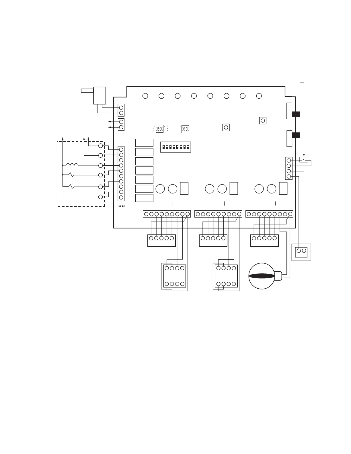
Multi-Sta
e: Wire the e
ui
ment as shown in Fi
. 14 usin
the
W2 terminal for second sta
e of heat and the W3 terminal for
third sta
e of heat. Wire the Y2 for second sta
e of coolin
.
Fig. 14. Heating and cooling equipment.
Wire the heat
um
to the e
ui
ment terminals on the
anel
as shown in Fi
. 15. Refer to manufacturer’s instructions for
additional wirin
instructions and substitute the TZ-3
e
ui
ment terminals for the thermostat terminals shown.
IMPORTANT
Some heat pump manufacturers (such as York and
Trane) use the B terminal as the transformer com-
mon. Do not connect the common from the equip-
ment to the zone control panel.
Two-s
eed Com
ressor: Wire the second sta
e com
ressor
to both Y2 and W2. Wire the auxiliar
heat to W3. Remove the
two-sta
e emer
enc
heat
um
er and install a
um
er from
W3 to E.
Fossil Fuel Kits with Heat Pum
s: Wire these s
stems like
Fi
.15 but use the manufacturer’s fossil fuel kit. Wire the
Trane XL 1800 and the TAYPLUS 103 as shown in Fi
. 16.
The recommended thermostat is theT8611G2051.
CGYRW
ZONE 1
THERMOSTAT
24V, 40 VA
TRANSFORMER
M19074
W2
W3
E
W1
B
G
R
O
Y1
Y2
TL
TL
2 STAGE
EM HEAT
MODEL TZ-3
CR
OC
OC
TR1
TR2
HEAT
TO TERMINAL AZ1 ON TAZ (IF USED)
OUTDOOR CONDENSING UNIT
HVAC CONTROLS
ZoneMAX
Add-A-Zone
TM
COOL PURGE FAN EM.HT ZONE 1 ZONE 2 ZONE 3
BOOT
OVERRIDE
PURGE
REMOTE OCCUPIED/
UNOCCUPIED CONTROL
(CLOSE IN UNOCCUPIED)
ON
OFF
Emergency Heat
ON
1
LW2 G Y R W M6 M4
M1
THERMOSTAT MOTOR
2 3 4 5 6 7 8
OCCUP
REMOTE
UNOCCUP
Zone-A-Lone
C
123X
456Z
GYRW
ZONE 3
THERMOSTAT
MODEL ARD OR
ZD DAMPERS
ZONE 2
LW2 G Y R W M6 M4
M1
THERMOSTAT MOTOR
ZONE 1
LW2 G Y R W M6 M4
M1
THERMOSTAT MOTOR
ZONE 3
CGYRW
ZONE 2
THERMOSTAT
123X
456Z
OPPOSED BLADE DAMPER MOTORS
AZ1
AZ2
TO TERMINAL AZ2 ON TAZ (IF USED)
ZoneMAX
TEMPERATURE
SENSOR
TM
15 MINUTES
10 MINUTES
5 MINUTES
20 MINUTES
25 MINUTES
30 MINUTES
STAGE TIMER
130 F
MAXIMUM
TEMPERATURE
120 F
110 F
140 F
150 F
160 F
W
W2
24V TRANSFORMER
FAN RELAY
HEAT RELAY
R
Y
Y2
C
G
 Loading...