Kit Instruction, continued
Page 2 of 2 Form 51-52-33-107
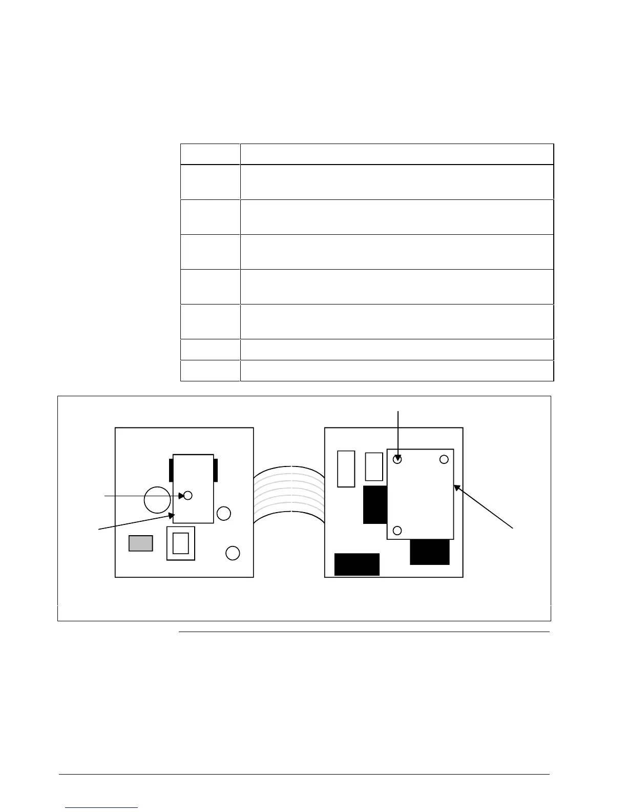
Installation Procedure Follow the procedure in Table 1 to install/replace a printed wiring
assembly in your controller. Refer to Figure 1 for location of components.
Table 1 – PWA Installation Procedure
Step Action
1
Remove the screw cover and loosen the screw on the front of
the controller. Pull the chassis from the case.
2
Remove the Main PWA from chassis by pushing up on
chassis guides and pulling the assembly out of the chassis.
3
Unfold the Main PWA with components facing up and lay
flat on table.
4
Insert the PWA provided in this kit in correct location
(Figure 1) by aligning connectors and inserting the standoffs.
5
Check product manual for assembly settings that should be
made.
6
Reinsert Main PAW into chassis, and chassis into case.
7
Configure unit per the manual and verify proper operation.
Standoff
Current
Out PWA
Aux Out / Dig In PWA
or
RS485/422 PWA
Standoff
Figure 1 – Component Location

 Loading...


