January 2017 51-52-33-137 2
Procedures:
The procedure tables that follow list the steps required to replace the old Printed Wiring Board in
your controller with the one supplied in this kit.
Table 1: How to Remove the Chassis
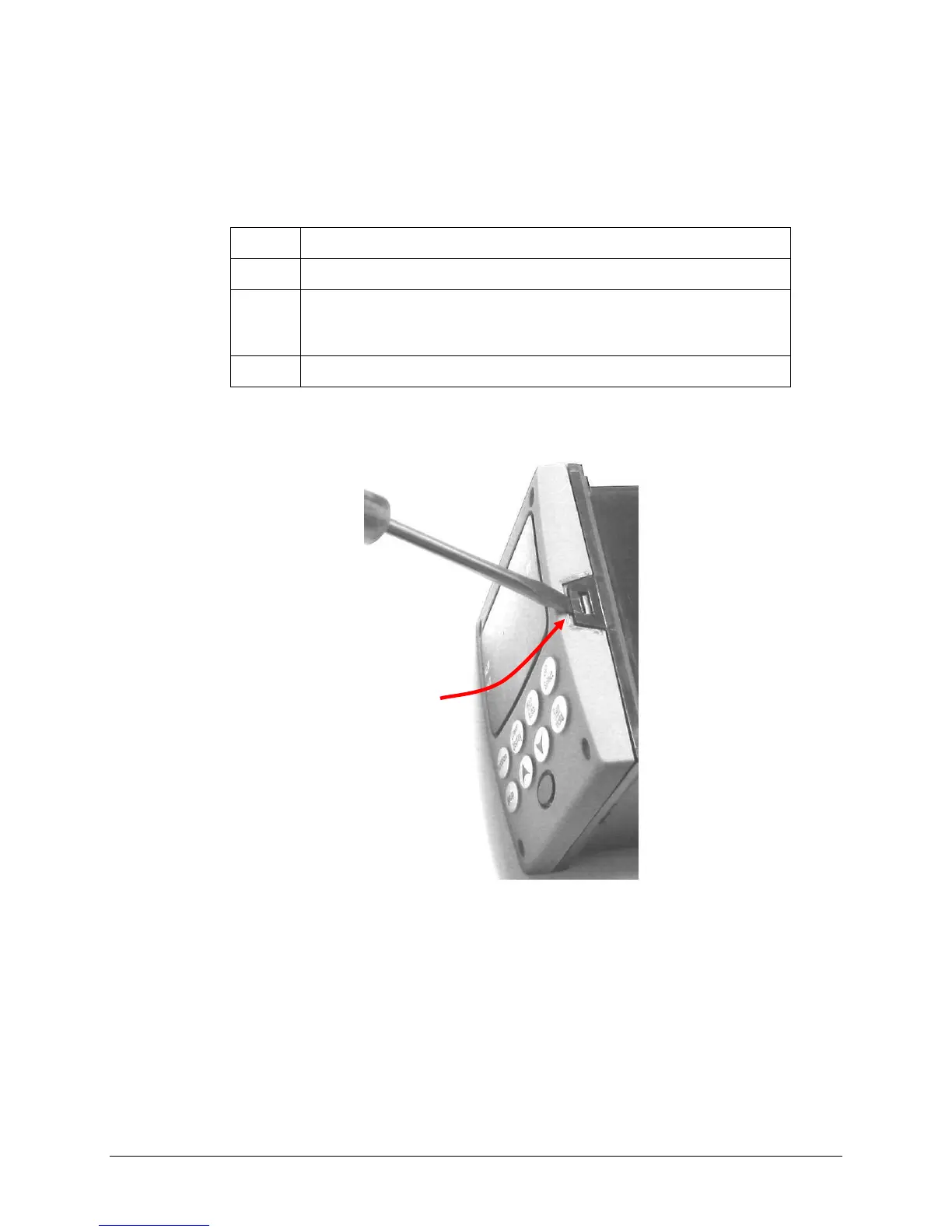
Remove any screws in the front face.
Insert a flat-bladed screwdriver into the tabs of the case as shown in
Figure 1 and pry chassis forward slightly until the chassis connectors
separate from the back of the case.
Grasp the bezel and pull the chassis out of the case.
Figure 1: Chassis Removal
Using a thin screwdriver, gently pry the side tabs from the front face and twist the screwdriver
slightly to disengage the front. Pry just enough to release it, otherwise you’ll bend or break
the tab. If you break or bend the tab and can’t reattach the front securely, you’ll need to reattach
the front using the 4 NEMA4 screws provided.
Insert thin screwdriver under
tabs and gently pry the tab and
twist slightly to disengage front.

 Loading...


