10 UDC3200 Universal Digital Controller Operator Manual 04/08
Separate External Wiring
Use Suppression Devices
ATTENTION
For additional noise information, refer to document number 51-52-05-01, How to Apply Digital
Instrumentation in Severe Electrical Noise Environments.
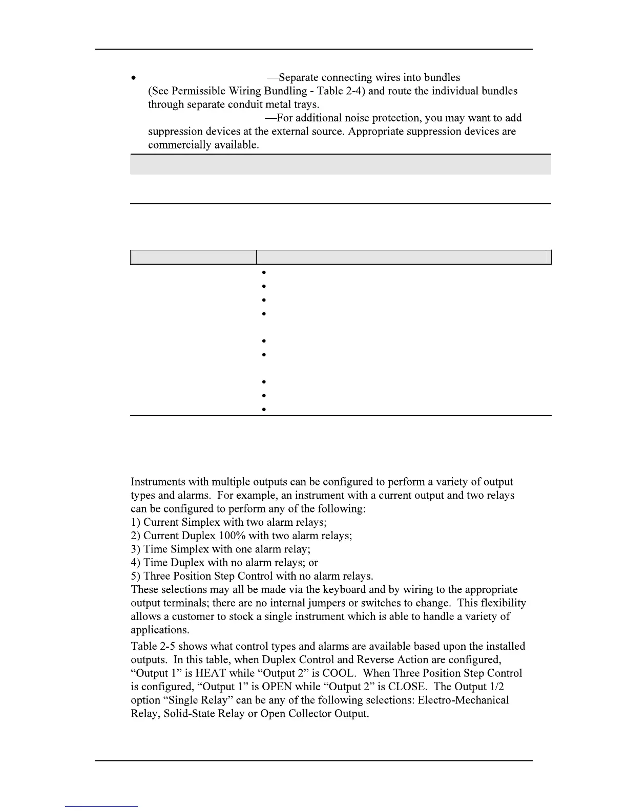
Permissible Wiring Bundling
Table 2-4 Permissible Wiring Bundling
Bundle No. Wire Functions
1
Line power wiring
Earth ground wiring
Line voltage control relay output wiring
Line voltage alarm wiring
2 Analog signal wire, such as:
Input signal wire (thermocouple, 4 to 20 mA, etc.)
4-20 mA output signal wiring
Digital input signals
3
Low voltage alarm relay output wiring
Low voltage wiring to solid state type control circuits
Low voltage wiring to open collector type control circuits
2.6 Wiring Diagrams
Universal Output Functionality and Restrictions
Table 2-5 Universal Output Functionality and Restrictions

 Loading...


