Section 3 - Installing the Control
3-17
Installing Output Devices
The VISTA-50P/VISTA-50PUL support up to 16
outputs. Each device must be programmed as to how to
act (ACTION), when to activate (START), and when to
deactivate (STOP). The 4204, and/or X-10 devices may
be used as output devices.
Installing the 4204 Relay Modules
Each 4204 module provides 4 relays with Form C
(normally open and normally closed) contacts.
The relay module will not operate until the
device address you have set the DIP switches
for is enabled in the control’s Device
Programming in the #93 Menu Mode.
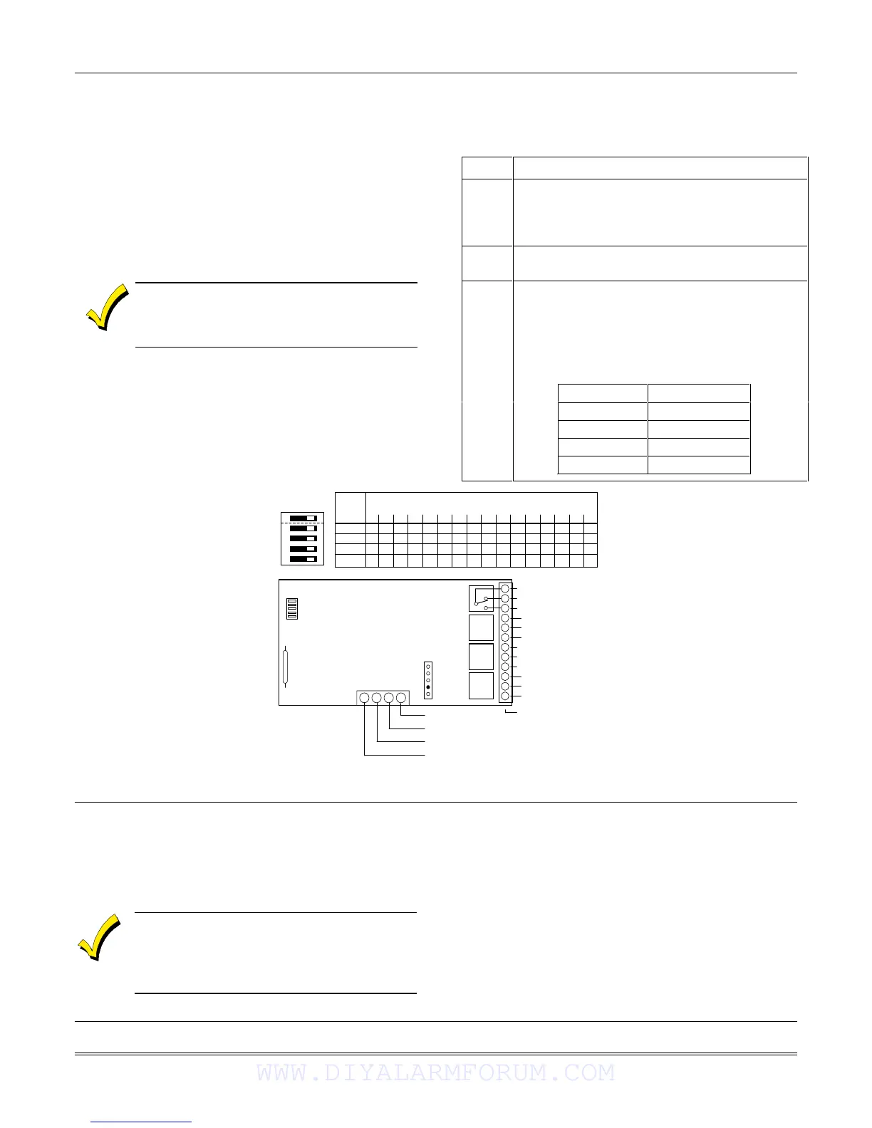
To install the relay modules, see Figure 3-21 and
perform the following steps:
Step Action
1 Set the 4204’s DIP switches for a device
address 01-15.
Do not use an address being used by another
device (keypads, RF receivers, etc.).
2 Mount the 4204 Module per the instructions
provided with them.
Connect the module’s wire harness to the
control (6, 7, 8, and 9). Plug the connector
(other end of harness) to the module.
If you are mounting remotely, homerun each
module to the control. The table below shows
the maximum wire run lengths.
Wire Gauge Maximum Length
#22 125 feet
#20 200 feet
#18 300 feet
#16 500 feet
3
SWITCH 4204 ADDRESS SETTINGS
POSITION ("—" means "OFF")
0 1 2 3 4 5 6 7 8 9 10 11 12 13 14 15
2
ON — ON — ON — ON — ON — ON — ON — ON —
3
ON ON ——ON ON ——ON ON ——ON ON ——
4
ON ON ON ON ————ON ON ON ON ————
5
ON ON ON ON ON ON ON ON ————————
ON
12345
➞
➞
➞
➞
➞
13 14 15 16
C
NC
NO
OFF
➞
ON
➞
DIP SWITCH
FOR SETTING DEVICE ADDRESS
AND ENABLING/DISABLING TAMPER
➞➞
COVER TAMPER (REED) SWITCH
➞➞
TB1
4204
TB2
4-PIN CONSOLE PLUG
➞➞
121110987654321
C
NC
NO
C
NC
NO
C
NC
NO
▲
RELAY
3
RELAY
2
RELAY
1
RELAY
4
TYPICAL
(SHOWN "OFF")
EITHER OR BOTH
CAN BE USED
➞➞
➞➞
DATA IN
FROM CONTROL
(–) GROUND
DATA OUT
TO CONTROL
(+) 12V
YEL
BLK
GRN
RED
Figure 3-21: 4204 Relay Module
Installing X10 Devices
X-10 devices are either plugged into standard AC
outlets or wired into the AC electrical system by a
licensed electrician, depending on the type of device
used.
Note each device’s House and Unit Code
setup, as these codes will be used to program
the devices in Output Programming in #93
Menu Mode described in the Programming
Guide.
X-10 devices require the use of a 1361X10 transformer
in place of the regular 1361 transformer.
X-10 devices respond to “on” and “off” commands sent
from the panel through the 1361X10 transformer.
To connect the 1361X10 transformer, see Connecting the
Transformer, later in this section.
WWW.DIYALARMFORUM.COM
 Loading...