VISTA-50P/VISTA-50PUL Installation and Setup Guide
3-18
Installing the Ground Start Module
U
L
The Ground Start Module is not intended for
use in UL Listed applications.
Output 1 may be used to trigger an optional 675
Ground Start Module for installations having telephone
lines that require ground start instead of loop start
operation to obtain a dial tone from the telco central
office.
When the panel has a message to transmit to the
central station, it seizes the line, goes off hook, and then
triggers the 675 Module to connect the RING side of the
telephone line to earth ground. The panel causes the
module to break the connection between RING and
earth ground when it obtains a dial tone.
To install the 675 Ground Start Module, perform the
following steps:
Step Action
1
Determine which side of the telephone line
is the RING side by connecting the (+) lead
of a DC voltmeter to earth ground, and the
(-) lead to one side of the telephone line.
The wire that reads + 50VDC is the
RING side.
2
Connect the 675 Ground Start Module to
the panel’s J7 connector trigger output 1, to
auxiliary power, and to the RING side of
the telephone line as shown in Figure 3-22.
3
Program field 1✳46 Auxiliary Output
Enable with a [0].
You cannot use Output 1 for the Ground Start if
you are using it for an Open/Close trigger or an
AAV module.
123456789
4142TR
CABLE
GRAY (GROUND)
YELLOW (OUT 1)
RED (OUT 2)
GREEN (GROUND)
BROWN (OUT 3)
BLUE (GROUND)
BLACK (OUT 4)
WHITE (GROUND)
J7 CONNECTOR
N/U
IF USED:
1. OUT 1 IS NO LONGER
USABLE FOR SMOKE DETECTOR RESET
(SEE FIELD 1*46).
2. OUT 2, 3, 4 CAN STILL BE
USED TO PROVIDE ALARM
STATUS INDICATIONS OR
TO OPERATE A KEYSWITCH
(SEE FIELD *15).
3. THE 675 IS NOT UL LISTED.
BROWN
GROUND START
TRIGGER
BLUE
GREEN
BLACK
VIOLET
TO AUX. POWER
TERM. 7
TO AUX. POWER
TERM. 6
(50mA CURRENT DRAW)
675
GROUND
START
MODULE
(CUT ORANGE
JUMPER)
TO
TELCO
RING
TO
EARTH
GROUND
Figure 3-22: Ground Start Module Connections
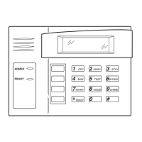
Installing a Remote Keyswitch
A UL-Listed remote keyswitch, such as the 4146, can be
used for remote arming/disarming of the burglary
portion of the system and for silencing alarms. The
keyswitch can operate in only one particular partition.
The keyswitch is wired across zone 7. This zone is no
longer available as a protection zone. Be sure to
program Zone 7 with a response type (e.g., type 10).
Operation
• A momentary short across zone 7 arms the
partition in the AWAY mode, and a short held for
more than 1/2 second arms the partition in STAY
mode 1. A subsequent short disarms the partition.
• The keyswitch LEDs indicate the partition’s status
(see table below).
• A momentary short across Zone 7 silences alarm
bell and keypad sounds, and disarms the system if
it was armed. A subsequent short across Zone 7
clears the alarm memory indication and resets 2-
wire smoke and glassbreak detectors (if used).
LED Indications
Green Red Indication
On Off Disarmed & Ready
Off Off Disarmed & Not Ready
Off On Steady Armed Away
Off Slow Flash Armed Stay
Off Rapid Flash Alarm Memory
The keyswitch reports as user 0, if Open/Close
reporting is enabled in field ✳40.
WWW.DIYALARMFORUM.COM
 Loading...