VISTA-50P/VISTA-50PUL Installation and Setup Guide
3-22
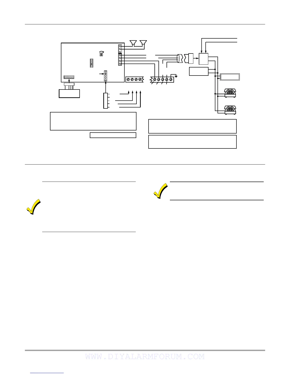
YELLOW
NO CONNECTION
RED
BLACK
GREEN
TO CONTROL PANEL
KEYPAD CONNECTIONS
KEYED
HEADER
123456 7
NO
CONNECTION
4286 VIP MODULE
ANSWERING
MACHINE
PREMISES
ANSWERING
MACHINE AND
PHONES
TIP
RING
RJ31X
JACK
TIP
RING
INCOMING TELCO LINE
CALLER ID
UNIT
IMPORTANT NOTE FOR EXISTING INSTALLATIONS:
EXISTING WIRES CONNECTED TO THE “HANDSET”
TERMINALS ON CONTROL MUST BE MOVED FROM
THERE TO TERMINALS 3 AND 4 ON THE 4286.
U.S. PATENT No. 4791658
THIS DEVICE COMPLIES WITH FCC RULES, PART 68
FCC REGISTRATION No. AC3USA-74659-KX-N
RINGER EQUIVALENCE: 1.0B
FOR COMPLETE INFORMATION, SEE INSTALLATION
INSTRUCTIONS N6431-3 ACCOMPANYING 4286 VIP
MODULE
GREY
BROWN
GREEN
RED
EARTH
GROUND
TIP RING TIP RING
4500
THERMOSTAT
GREEN
YELLOW
HANDSET INCOMING
TELCO LINE
NOTE:
4286 DEVICE
ADDRESS IS
FACTORY SET
TO “4”
SEE SPEAKER NOTE
SPEAKER NOTE: IF CONNECTING SINGLE SPEAKER, USE 8-ohm SPEAKER ONLY.
IF CONNECTING 2 SPEAKERS, USE 4-ohm or 8-ohm SPEAKERS
AND CONNECT IN SERIES.
SPEAKER
VOLUME
CONTROL
4286_wiring-002-V1
Figure 3-26: VIP Module Connections
Installing the Audio Alarm Verification Module
• 685 Receiver software must be rev. 4.6 or
higher. Earlier versions will not hold the
phone line connection.
• Contact ID code for “Listen-in to Follow” is
606. Contact ID is the only reporting format
that will send a “Listen-in to Follow.”
• If you are also using a 4285/4286 VIP
Module, be sure to follow Figure 3-29 when
making connections.
The UVS consists of a UVCM and at least one UVST.
The UVCM board has a DC power jack and a 34-
position terminal block for making connections to a DC
power source, UVSTs, telephone lines, music source, or
to the 4286 VIP Module; and to a control panel’s voice
trigger and bell outputs (if required). Refer Figure 3-28
for wiring connections. For a detailed explanation of
the wiring connections and the functions of the DC
power jack and terminal block positions, refer to the
installation instructions that accompany the UVS.
If the phone plug is disconnected from the
control, the premise’s phones will not operate.
NOTES:
• When the AAV indicates that the audio alarm
verification session is completed, all keypad sounds
are restored. Sirens are restored if the alarm
timeout period has not expired.
• As part of its fail-safe software, the control limits
all audio alarm verification sessions to 15 minutes.
This is because once the session begins, the AAV
Module controls the duration.
• If a new Fire alarm should occur during a session,
the control breaks the phone connection and sends
the new Fire Alarm report, then re-triggers the
AAV Mode. All other dialer messages triggered
during ongoing conversation are held until either
the AAV Module signals that it is inactive, or the
15-minute timeout occurs.
WWW.DIYALARMFORUM.COM
 Loading...