Do you have a question about the Honeywell WATCHDOG III and is the answer not in the manual?
General safety instruction before installation and operation.
Defines symbols used for actions and instructions in the manual.
States no liability for damage due to non-compliance.
Explains how DANGER, WARNING, and CAUTION are indicated.
Prohibits technical changes and mandates OEM parts.
Configuration and function of the R1 flame relay.
Configuration and function of the R2 alarm relay.
Diagram illustrating terminal connections on the P222 processor.
Indicates the connection point for the viewing head.
Details the AC and DC power input requirements for the P222.
Instructions for connecting power and signals to the P222.
Steps for physically attaching the viewing head connector.
Guidelines for choosing an optimal installation site for the viewing head.
Procedures for aiming the viewing head for accurate flame detection.
Describes the system's self-test and error indication.
Overview of all LEDs, displays, and push buttons on the processor.
Guides for setting R1 and R2 relay delays.
Steps for manually setting the UV signal gain.
Using Gain Set for adjusting the 4-20mA output.
Procedure to switch between 0-20mA and 4-20mA outputs.
How to check viewing head temperature and warnings.
Configuration of Modbus RTU settings like baud rate and address.
List of internal registers accessible via Modbus.
Visual guide for programming the UV gain parameter.
Visual guide for programming relay settings and checking temperature.
Troubleshooting when P222 displays 'S256'.
Troubleshooting when P222 displays 'loop'.
Diagnosing loss of flame signal, likely due to misalignment.
Specifications for AC and DC power input.
Ambient temperature ranges for processor and viewing head.
Details of relay contacts and analog output specifications.
Specifications for manual clear and channel select inputs.
Supported serial communication protocols and baud rates.
Details on viewing distance, field of view, and cable requirements.
Physical dimensions of the viewing head and mounting yoke.
List of CSA standards the product complies with.
Guidelines for disposing of electronic components according to WEEE.
The Honeywell "WATCHDOG III" Flare Stack Monitoring System is an electro-optical device designed to reliably detect the presence or absence of a flame at a flare tip. It utilizes an ultraviolet (UV) sensor to monitor the UV energy emitted by the flame. When UV energy is detected, the system indicates the presence of a flame. Conversely, if no flame is detected, two flame-proving relays will de-energize after a user-selected time delay.
This system is engineered to operate effectively under typical and harsh environmental conditions. The UVTron sensor in the S256BE viewing head is designed not to respond to wavelengths beyond 300nm, meaning it is unaffected by sun radiation. This allows the S256BE to be mounted anywhere around the flare stack, even when aiming directly towards the sun. The UVTron also performs satisfactorily in heavy rain, snow, dust storms, and fog. If the flare flame is visible to the human eye from the viewing head's location, the S256BE will function effectively.
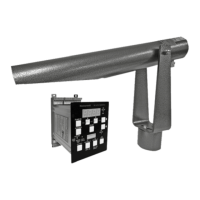
The system comprises three main components: the S256BE viewing head, the P222 signal processor, and an ASY55XBE cable/connector assembly. The S256BE viewing head is designed for ground-mounting, allowing for easy access for maintenance personnel without interrupting flare stack operations. It can be positioned up to 1000 feet (300 meters) from the flare tip.
The P222 signal processor features a front panel with LED indicators, a four-digit display, and push buttons for configuration and operation.
| Temperature Accuracy | ±0.5 °C (±0.9 °F) |
|---|---|
| Measurement Parameters | Temperature, Humidity |
| Humidity Range | 0 to 100 %RH |
| Display | LCD |
| Communication Interface | RS-485 |