“WATCHDOG III” Flare Stack Monitoring System · Edition 01.24
EN-2
2 CHECKING THE USAGE
The “WATCHDOG III” Flame Monitoring System exists of three
components:
1 the Model S256BE viewing head,
2 the Model P222 signal processor,
3 one of the following ASY55XBE cable/connector assemblies
with over-molded 4-pin connector with C330S cable:
– ASY55XBE: cable length 50'
– ASY55XBE-100: cable length 100'
– ASY55XBE-200: cable length 200'
– ASY55XBE-300: cable length 300'
The “WATCHDOG III” Flare Stack Monitoring System electro- opti-
cally detects the presence or absence of a flame at the flare tip.
The System's ultraviolet sensor dependably and reliably monitors
the amount of ultraviolet energy being emitted by the flame.
When ultraviolet (UV) energy from the flame is detected, the
System indicates that the flame is present. When no flame is
detected, two flame proving relays with adjustable flame failure
response time will be de- energized after the user-chosen time
delay expires.
The “WATCHDOG III” Flare Stack Monitoring System is designed
to operate under typical and harsh conditions that may be
present. The UVTron sensor used in the S256BE viewing head
does not respond beyond wavelengths of 300nm; sun radiation
is beyond 300nm. The response range allows the S256BE to be
mounted anywhere around the flare stack - even when aiming
straight towards the sun. The UVTron will work satisfactorily under
heavy rain, snow, dust storms and fog. If the human eye can
detect the flare flame from the viewing head location, the S256BE
will perform satisfactorily. The R1 flame relay includes an adjust-
able delay of 0-60 seconds and may be used for relighting the
pilot. The R2 flame relay includes an adjustable delay of 0- 3,600
seconds.
The S256BE is ground-mounted. The distance from the flare tip
to the viewing head can be up to 1000feet (300 meters), allow-
ing the system to be installed, operated and maintained without
interrupting the operation of the flare stack. Because the S256BE
viewing head is ground mounted, it allows maintenance personnel
easy access, should servicing be required.
3 INSTALLATION
3.1 Power Requirements
The P222 can be powered from an AC Line Voltage between 85
to 264VAC at 47 to 440Hz., or from an external 24VDC power
supply. A 30W power supply is sufficient to power both the signal
processor and viewing head.
The viewing head is powered by the P222 signal processor via a
0.25A self-resetting fuse. The power to the signal processor itself
is via a 0.75A self-resetting fuse. These self-resetting fuses are
reset when power to the signal processor is removed.
3.2 Signal Processor Wiring
The P222 signal processor should be mounted in a suitable
weatherproof and/or hazardous location enclosure as required by
the application.
Refer to page 2 (3.2.3 Terminal labeling), and proceed to wire
the signal processor as follows:
AC Powered System
Terminals are located on the top left of the unit.
1
Connect AC Line (hot) power supply to terminal AC1
2
Connect AC Neutral (or return to line power supply) to terminal
AC2
3
Connect Ground to terminal GND. Local codes may require
additional wiring requirements. Follow all installation site local
jurisdiction requirements.
DC Powered System
Terminals are located on the top left of the unit.
1
Connect +24VDC power to +24V IN
2
Connect -24VDC power to GND
3.2.1 Relay R1 and Connections
Relay R1 will energize when flame is detected, and de- energize
when flame has not been detected for R1 TRIP DELAY seconds.
When energized, the R1 RELAY ON Led on the front panel will be
illuminated. Often the flame relay R1 is used to trigger an ignition
system to re-ignite the flame. It could also serve to trigger an
alarm as a warning of loss of pilot. Two sets of Form C (SPDT)
contacts are provided (DPDT). One set may be used for re- light-
ing the pilot and the second may be used for alarm.
Connections to this relay are made on the top right terminal con-
nectors.
R1A COM and R1B COM are the common terminals, with R1A
ON and R1B ON being closed for Flame On, and R1A OFF and
R1B OFF being closed for Flame Off.
3.2.2 Relay R2 and Connections
Flame relay R2 is typically used for alarm indication. The time
delay for relay R2 must be longer than the time delay for relay R1.
When the pilot flame is detected, the relay energizes immediately
and provides a FLAME ON indication. The R2 RELAY ON LED
on the front panel will be illuminated. When a flame is no longer
detected, the R2 relay de-energizes after its adjustable R2 TRIP
DELAY time, which must be longer then the R1 TRIP DELAY time.
Connections to this relay are made to the top center terminal con-
nector. One set of Form C contacts are provided (SPDT).
R2 COM is the common terminal, with R2 ON being closed for
Flame On (Delayed), and R2 OFF being closed for Flame Off
(Delayed).
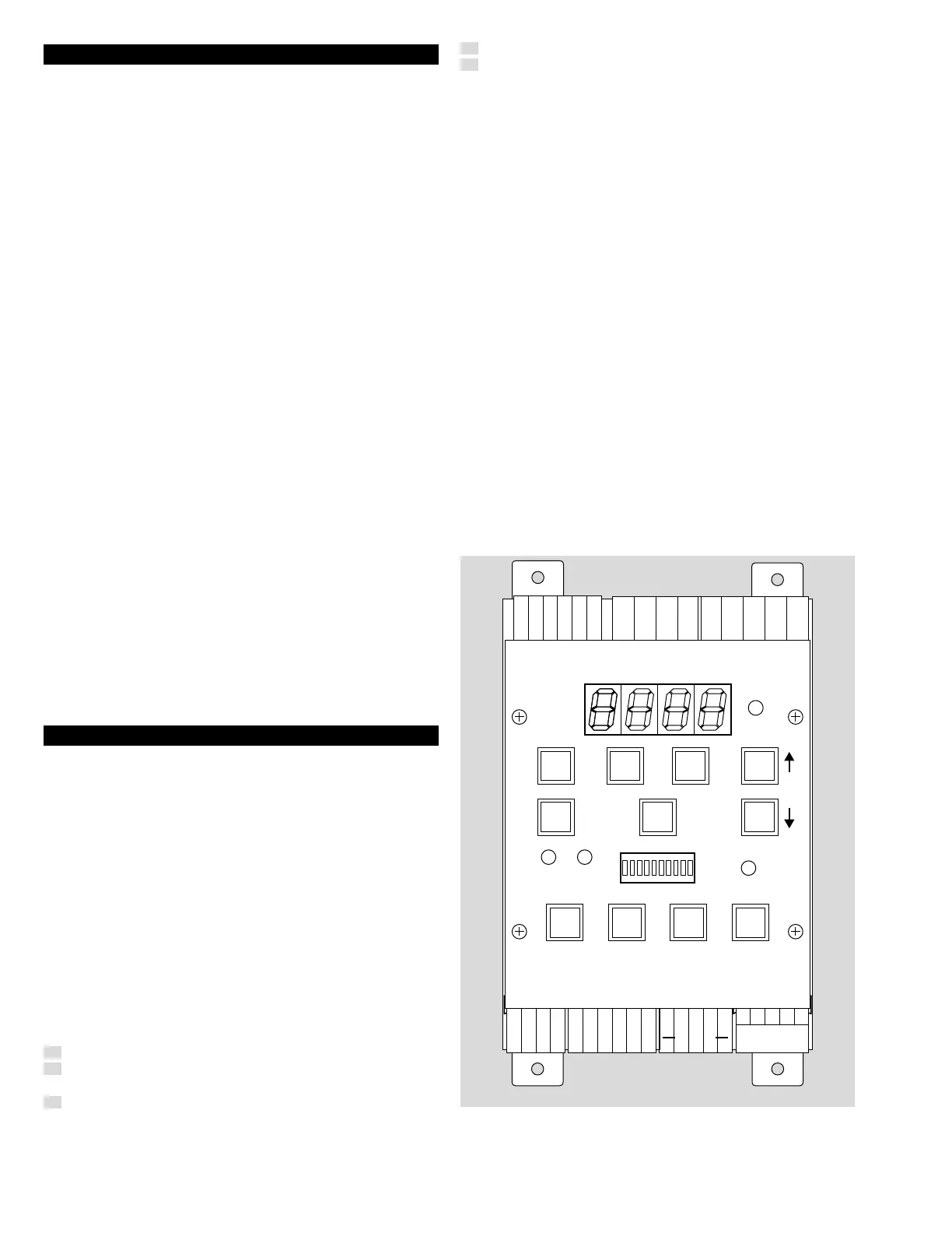
3.2.3 Terminal labeling
M33508
GND
GND
R2 COM
R2 OFF
R2 ON
R1A COM
R1A OFF
R1A ON
R1B ON
R1B OFF
R1B COM
+24V
IN
+24V
OUT
AC1
AC2
R1
RELAY
ON
R2
RELAY
ON
A B
FLAME ON
AUTO/MAN STORE
NO
SET YES
AUTO/ON
FLASH
(RESET
REQ)
MANUAL
(HAND)
OFF
SELF
CHECK
GAIN SET RESET
R1
TRIP DELAY
R2
TRIP DELAY
+TX
- TX
- RX
+ RX
GND
GND
GND
+V
SC
SIG
SIG
GND
MAN
CLEAR
+
+
B
RMT
METER
CHAN
SEL
SENSOR
3.2.4 Viewing Head Connections
Connections to the viewing head are made to the connector on
the bottom right.

 Loading...


