“WATCHDOG III” Flare Stack Monitoring System · Edition 01.24
EN-6
4.4.5 Registers Map
40001 R/O Flame Count
40002 R/O
0 Channel
0=Chan A
1= Chan B
1 Delayed relay R2 Relay R2
2 Lockout
Processor
lockout status
0 = lockout
3 Panel access Disabled = 0
4 Ma out type 1 = 4 to 20
5 Early relay R1 Relay R1
40003
R/W
Flame on channel A (0 -> 2999)
40004
R/W
Flame on channel B (0 -> 2999)
40007
R/W
Ma out gain channel A (0 - 99)
40008
R/W
Ma out gain channel B (0 - 99)
40012
R/W
UV tube gain channel A (0 - 99)
40016
R/W
UV tube gain channel B (0 - 99)
40017 R/O Viewing head A type
40018 R/O Viewing head B type
40019 R/O Temperature viewing head A
40020 R/O Temperature viewing head B
40021
R/W
Delay time R2 Chan A 1 to 3600
40022
R/W
Delay time R1 Chan A 1 to 60
40023 R/O Version
40024 R/O 222
40034
R/W
Delay time R2 Chan B 1 to 3600
40035
R/W
Delay time R1 Chan B 1 to 60
40062 R/O
Operational time in 2 hr
increments
4.5 Programming for the “WATCHDOG III” Flare Stack Mon-
itoring System
Always disconnect and reconnect the viewing head while the
signal processor power is disconnected. Connecting the viewing
head while the P222 is “hot” may damage the unit and will not
allow the processor to communicate with the viewing head.
Refer to page 4 (4.2 Front Panel LED Indications and Push
Button Functions) for the P222 LED, display and push button
functions.
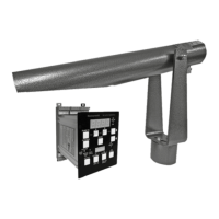
4.5.1 Flow Chart – Programming UV Gain
M33539
Press „A“ and „B“
Button to manually
adjust UV Gain or
select default value
„ADJ?“
Make Gain
Adjustment?
Press Button „B“
„AUXX“
Adjust UV Gain
(00–99)
Download
Default Values
Press „B“ Button
(YES) to store
New Values
New value
stored as
displayed by
– – – –
Press UP/DOWN
Button to set
New Values
Press „B“ Button
(YES) to store
New Values
New value
stored as
displayed by
– – – –
Resume Operation with New Data
downloaded to the System
Yes
Yes
Yes
No
No
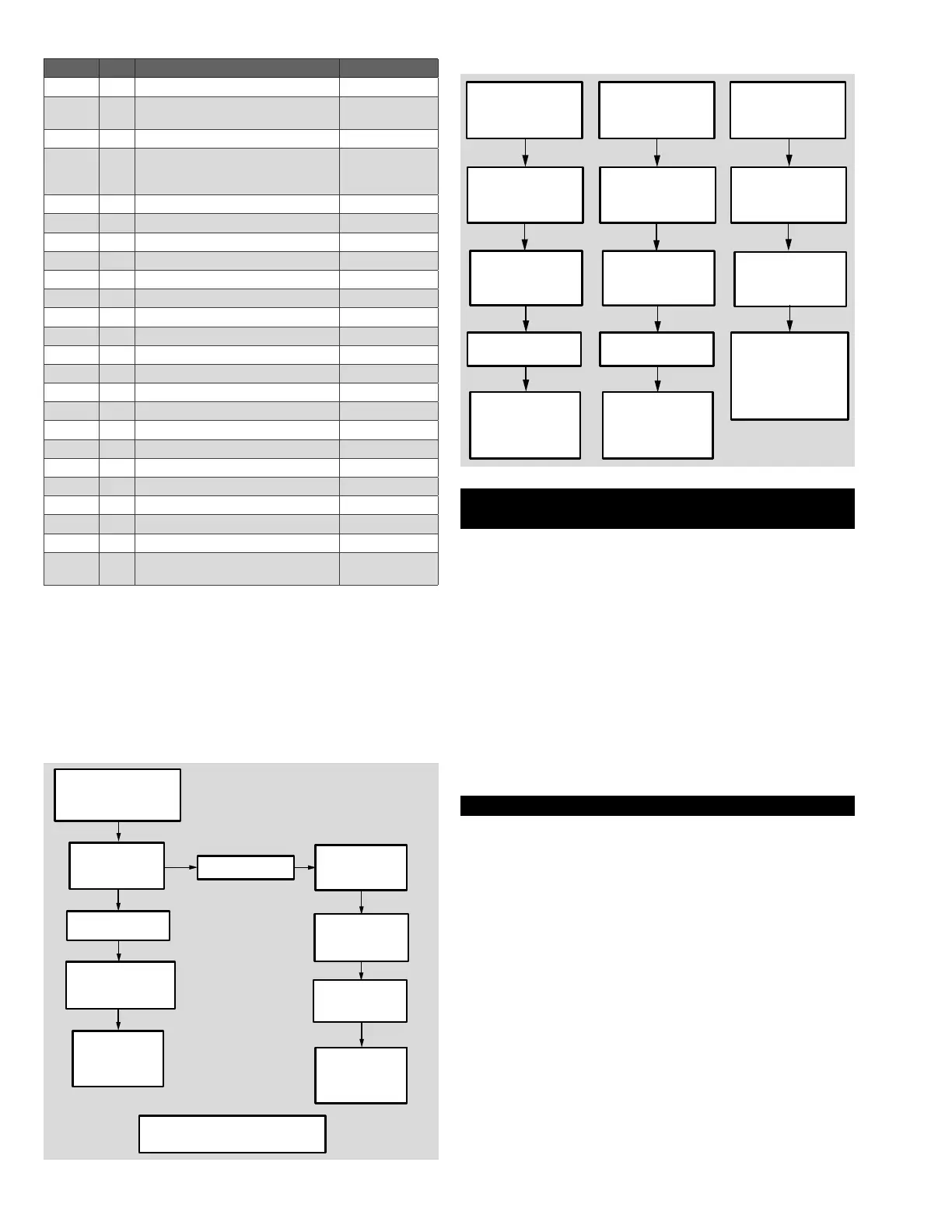
4.5.2 Flow Chart – Programming Relay Settings, checking
Viewing Head Temperature
M33540
To Adjust
R1 Relay
Settings
To Adjust
R2 Relay
Settings
To Check Viewing
Head Temperature
Press R1 Relay
SETUP Button
Press R2 Relay
SETUP Button
Simultaneously
Press RESET and
DOWN Button
Press UP/DOWN
Button to make
Adjustment
Press UP/DOWN
Button to make
Adjustment
4 Digit Display Unit
displays Viewing
Head Temperature
Press STORE
Button
Press STORE
Button
NOTE: Temperature
above 80°C
(176°F) will
be displayed in
Flashing Mode
New Value stored
as displayed by
– – – –
New Value stored
as displayed by
– – – –
5 ASSISTANCE IN THE EVENT OF MALFUNC-
TION
5.1 P222 display shows S256
On power up, the P222 signal processor should display the cur-
rent software version and “S256” if the viewing head connections
are correct. If the display shows “0000” the most likely cause is a
missing source impedance matching resistor. Refer to the Viewing
Head Connections section.
5.2 P222 display shows loop
On power up if the display shows “loop”, and older version of the
signal processor is being used. Install a jumper across the external
meter connections GND and RMT+.
5.3 Flame Signal is lost
If the system has been operational and the flame signal is lost (as-
suming the flame signal is still present), the likely cause is improper
S256BE viewing head aim due to movement/misalignment.
6 TECHNICAL DATA
6.1 Electrical Input to Processor
AC Power: 85 to 264VAC, 47 to 440Hz
300mA maximum with viewing head connected
DC Power (As Main Power): 22 to 26VDC, 300mA
maximum with viewing head connected
DC Backup Power: 22 to 24VDC, 300mA with viewing head
connected. Backup and main power can be connected simulta-
neously.
6.2 Environmental
Model P222 Signal Processor: Ambient Temperature: 0° C to
60° C (32° F to 140° F)
Model S256BE Viewing Head:
Ambient Temperature: -40° C to 80° C (-40° F to 176° F)
Viewing head housing: NEMA type 4X / IP66
6.3 Outputs
Relay R1: 2 Form C contacts, adjustable delay of 0-60 seconds
Contact Ratings: 5A at 30VDC or 250VAC
Relay R2: 1 Form C contact, adjustable delay of 0-3600 seconds
Contact Ratings: 5A at 30VDC or 250VAC
Analog Flame Signal: 0 to 19.8mA output for remote meters, or
4 to 19.8mA output (360 ohm max resistance)
 Loading...


