EXCEL 500/600 - INSTALLATION INSTRUCTIONS
19 EN1R-1047GE51 R0913
Line Power Supply
WARNING
A separate CRT 6 or 1450 series (U.S.) transformer must be
used for each of the EXCEL 500/600 controller's 24 V
supplies.
No additional loads may be connected!
Each additional XL500/600 controller requires its own
transformer.
An additional transformer, appropriate to the power require-
ments, should be used to power input/output peripherals (e.g.
actuators). See also Fig. 41.
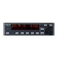
PRIMARY VOLTAGE SECONDARY VOLTAGE
TRANSFORMER (CRT)
Fig. 42. Excel 500/600 power supply (CRT)
To avoid interference, the cable between the transformer and
the power supply module should be kept as short as possible
(max. 6 ft [2 m]). The transformer should therefore be
positioned close to the power supply module.
Fuse the transformer primary with its own fast-acting 10 A
back-up fuse (or H 16 or L 16 miniature circuit breaker).
The primary coil of the CRT 6 contains a 0.8 A / 250 V quick-
blow fuse.
Table 5 gives an overview of the transformers of the 1450
series (U.S.):
Table 5. 1450 series transformers data
part #
1450 7287
primary side secondary side
-001 120 Vac 24 Vac, 50 VA
-002 120 Vac
2 x 24 Vac, 40 VA, and 100 VA
from separate transformer
-003 120 Vac
24 Vac, 100 VA, and 24 Vdc;
600 mA
-004 240/220 Vac 24 Vac, 50 VA
-005 240/220 Vac
2 x 24 Vac, 40 VA, and 100 VA
from separate transformer
-006 240/220 Vac
24 Vac, 100 VA, and 24 Vdc;
600 mA
The 1450 series includes built-in fuses, line transient /surge
protection and AC convenience outlet, it meets NEC class 2
requirements.
XC6010 Computer Module
CAUTION
Do not unplug the CPU module with the power still
connected, since this could destroy the module. First,
switch S1 on the power supply module to the 0
position.
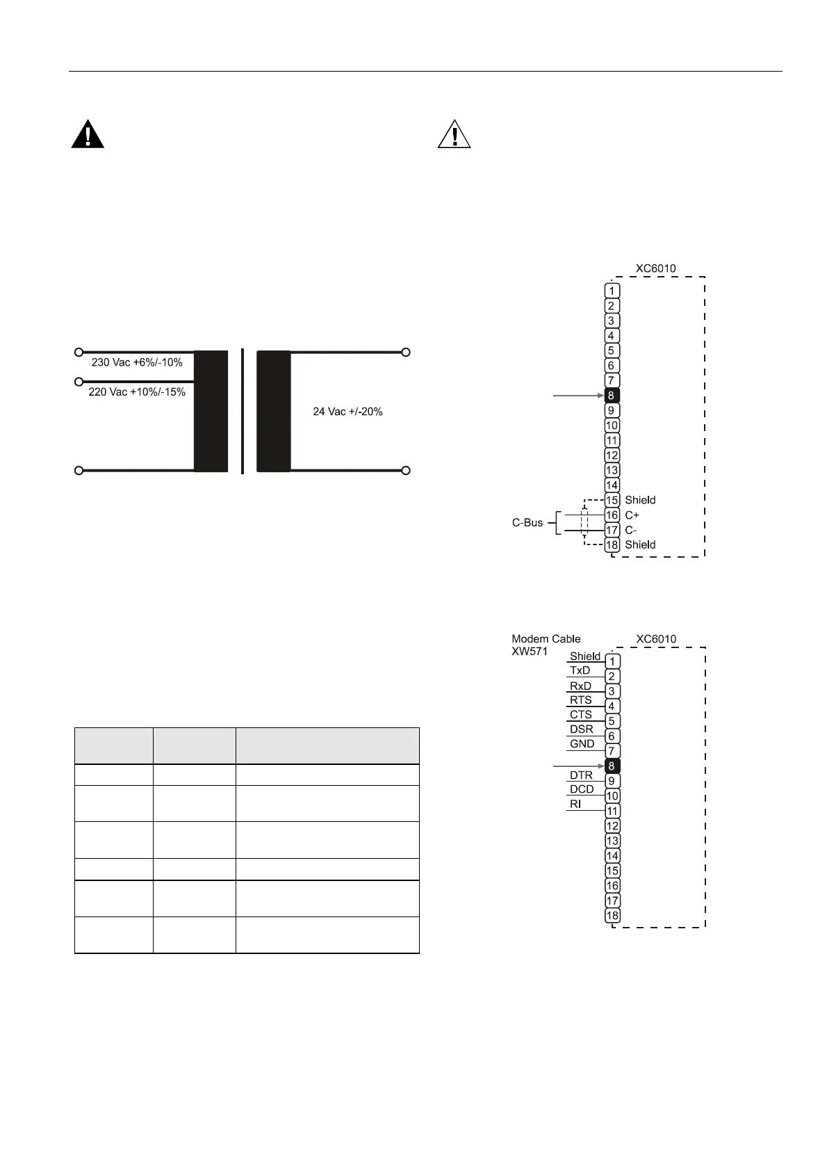
If one of the C-bus submodules XD505A or XD508 is installed
on the XC6010, follow Fig. 43.
Fig. 43. Excel 600 CPU module C-Bus connections
The system bus is connected to terminal 16 (C+) and terminal
17 (C-). See also section "C-Bus Termination (XC6010)" on
page 33.
Fig. 44. Excel 600 CPU modem connection
The XC6010 has two EPROMs for the operating system and
one flash EPROM for the application software. Their locations
are shown in Fig. 45.
 Loading...