EXCEL 500/600 - INSTALLATION INSTRUCTIONS
EN1R-1047GE51 R0913
26
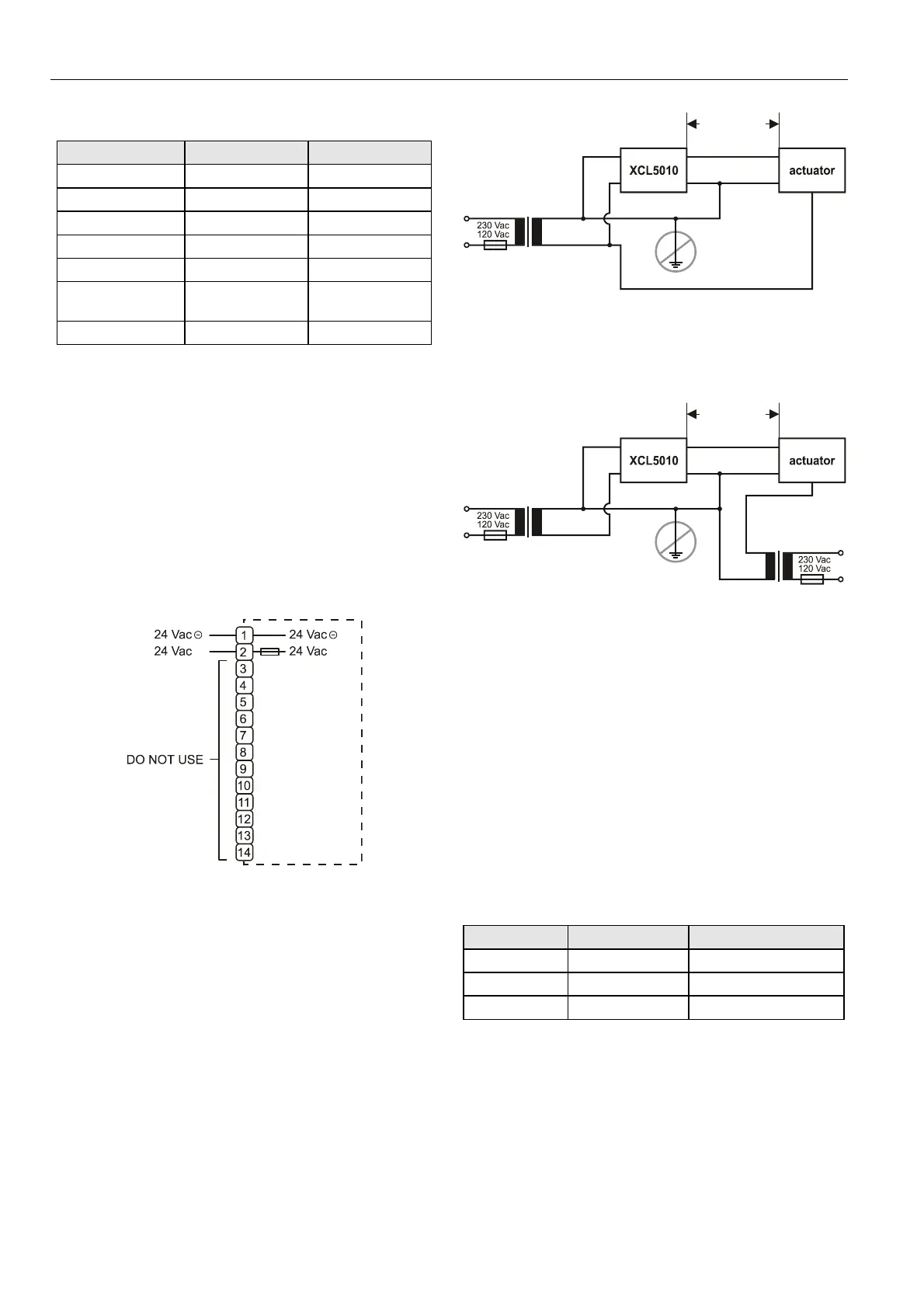
Table 10. Signals of serial port
signal type controller output controller input
signal ground
transmit x
receive x
carrier detect x
clear to send x
data terminal
ready
x
5 V x
MMI Connection
For direct communication the external operator interface
XI582 and the XL-Online PC MMI can be connected to the
serial port.
Power Supply
The XCL5010 is powered by an external transformer.
IMPORTANT
Only the terminals 1 and 2 of the terminal block may
be used for power supply. Do not wire any of the
terminals 3 to 14.
Fig. 61. XCL5010 power terminals location
Terminal 2 is protected by a 4 A quick-acting fuse.
Transformer requirements for one XCL5010:
Voltage: 21…30 Vdc or 24 Vac ± 20%
Current: 5 VA
The transformer, already installed in the cabinet, can be used
to supply several controllers, communication devices, or peri-
pherals like actuators, etc. if the transformer provides
sufficient power.
TRANSFORMER
PRIMARY
VOLTAGE
24 Vac
24 Vac
GND
Y (0...10 Vdc)
GND
max. 170 m
min. 0.75 mm
2
Fig. 62. Power for XCL5010 with 24 V actuator (single
transformer)
TRANSFORMER
TRANSFORMER
PRIMARY
VOLTAGE
PRIMARY
VOLTAGE
24 Vac
24 Vac
GND
GND
Y (0...10 Vdc)
GND
max. 400 m
min. 0.75 mm
2
Fig. 63. Power for XCL5010 with 24 V actuator (separate
transformer)
Use quick-acting backup fuse 10 A (or automatic H16 or L16)
to protect transformer primary side. On the primary side of the
CRT 2, there is a fusible output of type M 0.315 A (T) 250 V
for the purpose of fine fusing.
NOTE: When selecting the appropriate transformer, con-
sider the number of Distributed I/O modules (see
worst-case power consumption information below) to
be used as well as the power requirements of all
active sensors and actuators connected to the
transformer.
CRT-Series
Table 11. Overview of CRT Series AC/DC current
transformer max. AC current max. DC current
CRT 2 2 A 0.5 A = 500 mA
CRT 6 6 A 1.3 A = 1300 mA
CRT 12 12 A 2.5 A = 2500 mA
 Loading...