EXCEL 500/600 - INSTALLATION INSTRUCTIONS
21 EN1R-1047GE51 R0913
L1
LA1
LA2
LA3
LA4
LA5
L2
L3
L4
L5
L6
XC 5010C
RS232
LA1: Wink LED
LA2: C-Bus transmit
LA3: C-Bus receive
LA4: Not used
LA5: Not used
L1: Normal
L2: System error
L3: RS232 transmit
L4: RS232 receive
L5: Not used
L6: Ground loop
RESET BUTTON
FRONT
REAR
Fig. 48. Excel 500 CPU module front panel
The operator interface on the front of the CPU modules
allows connection of the Xl581/XI582 Operator Interface or
the XL-Online PC MMI. As an option, the XI582 can be
connected at the rear of the XC5010C. When connecting at
the rear, the switch on the front panel of the XC5010C must
be set to "Rear".
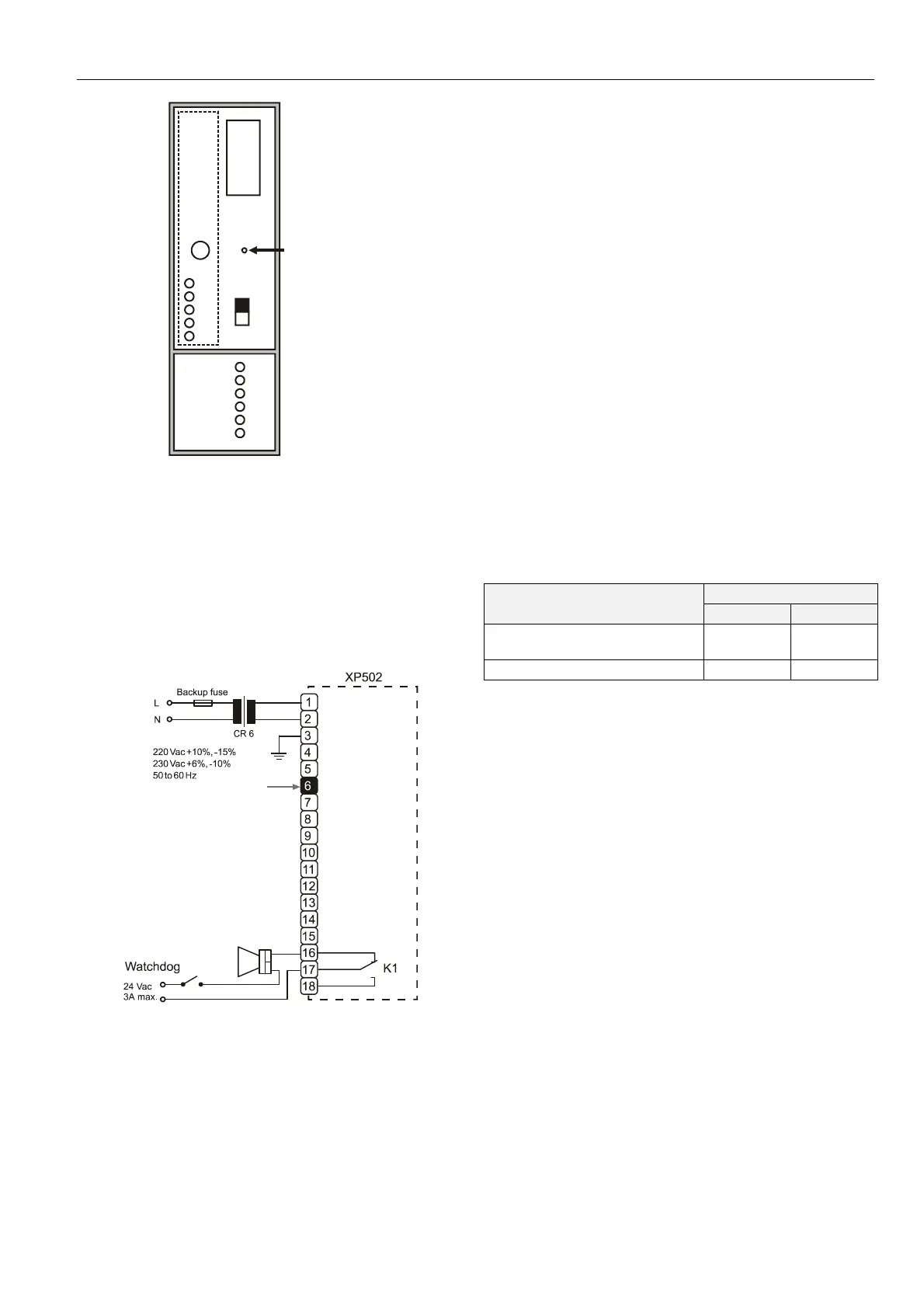
XP502 Power Supply Module
Fig. 49 shows the pin-out of the XP502 Power Supply
module.
Fig. 49. XP502 Power supply module and watchdog
circuit
To monitor the line power supply, the watchdog alarm must
be provided with its own power or battery supply.
Controller in operation: Watchdog relay terminals 17 and 18
connected.
Controller non-operational: Watchdog relay terminals 16
and 17 connected.
RIN-APU24 Uninterruptable Power Supply
The RIN-APU24 Uninterruptable Power Supply can be wired
to an XP502 in order to power XC5010C/XC6010 controllers.
In this context, a distinction must be made between the
following three different possible cases:
wiring of the RIN-APU24 to an XP502 powering
XC5010C/XC6010 controllers equipped with internal
modules, but not connected to Distributed I/O's;
wiring of the RIN-APU24 to an XP502 powering
XC5010C controllers connected to Distributed I/O's, but
not equipped with internal modules; and
wiring of the RIN-APU24 to an XP502 powering
XC5010C controllers equipped with internal modules and
connected with Distributed I/O's.
Further, in the case of the XCL5010, the RIN-APU24 can
provide power directly (i.e. without recourse to an XP502). In
this case, no distinction need be made between controllers
with (or without) internal modules and/or connected (or not
connected) to Distributed I/O's.
Table 6. Power consumption of Excel 500 controllers
devices powered
supply voltage
24 Vdc 28.8 Vdc
XP502, XC5010C, XI581
(backlight ON)
170 mA 155 mA
XP502, XC5010C 140 mA 130 mA
See also RIN-APU24 Uninterruptable Power Supply –
Mounting Instructions (MU1B-0258GE51) for detailed wiring
diagrams covering all of the aforementioned cases.
XF521A Analog Input Module
Technical Specifications
Number:
eight inputs (AI1 – AI8)
Input:
0...10 Vdc (low-input impedance, 25 kΩ to 10 V /
200 kΩ to GND);
0...20 mA (via external 500-Ω resistor);
4...20 mA (via external 500-Ω resistor);
NTC 20 kΩ(-50...+150 °C);
PT1000 (-50...+150 °C)
Protection:
up to 40 Vdc / 24 Vac
Resolution:
12-bit resolution
Accuracy:
±75 mV or 0.75% (0...10 V)
 Loading...