Page 10
DIMENSIONS & INSTALLATION
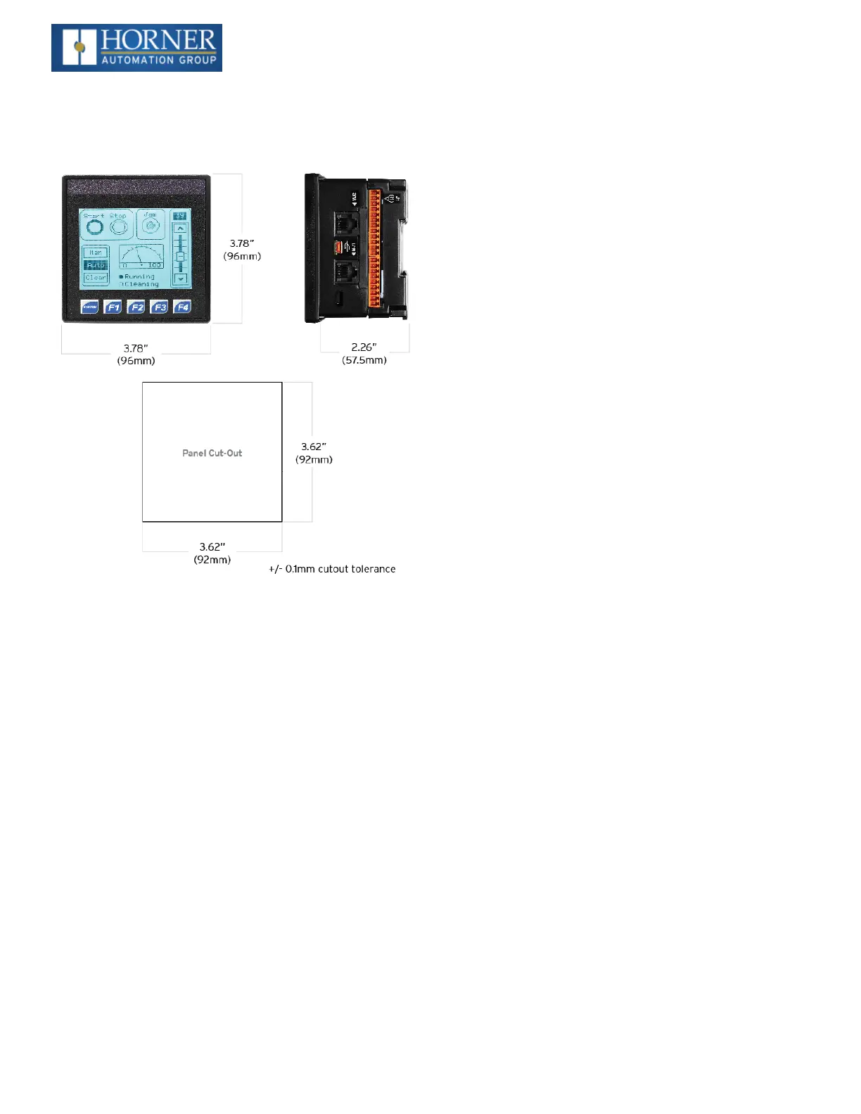
Dimensions & Panel Cutout
Installation Information
l
The XLE/XLT utilizes a clip installation method to
ensure a robust and watertight seal to the enclosure.
Please follow the steps below for the proper install-
ation and operation of the unit.
l
This equipment is suitable for Class I, Division 2,
Groups A, B, C and D or non-hazardous locations
only.
l
Digital outputs shall be supplied from the same
source as the operator control station.
l
Jumpers on connector JP1 shall not be removed or
replaced while the circuit is live unless the area is
known to be free of ignitable concentrations of flam-
mable gases or vapors.
l
WARNING- The USB ports are for operational main-
tenance only. Do not leave permanently connected
unless area is known to be non-hazardous.
Installation Procedure
1. Carefully locate an appropriate place to mount the
XLE/XLT. Be sure to leave enough room at the top of
the unit for insertion and removal of the microSD™
card.
2. Carefully cut the host panel per the diagram, cre-
ating a 92mm x 92mm +/-0.1 mm opening into which
the XLE/XLT may be installed. If the opening is too
large, water may leak into the enclosure, potentially
damaging the unit. If the opening is too small, the
OCS may not fit through the hole without damage.
3. Remove any burrs and or sharp edges and ensure
the panel is not warped in the cutting process.
4. Remove all Removable Terminals from the
XLE/XLT. Insert the XLE/XLT through the panel
cutout (from the front). The gasket must be between
the host panel and the XLE/XLT.
5. Install and tighten the four mounting clips (provided
in the box) until the gasket forms a tight seal (NOTE:
Max torque 0.8 to 3 Nm, or 7-10 in-lbs).
6. Reinstall the XLE/XLT I/O Removable Terminal
Blocks. Connect communications cables to the
serial port, USB ports, Ethernet port,and CAN port
as required.
Battery Maintenance
The XLE/XLT uses a replaceable non-rechargeable 3V Lith-
ium coincell battery (CR2450) to run the Real-Time Clock
and to keep the retained register values. This battery is
designed to maintain the clock and memory for 7 to 10
years. Please reference MAN0878 providing instructions
on how to replace the battery.

 Loading...

