Page 9
COMMUNICATIONS
Serial Communication
MJ1 Wiring
RS-232 with full handshaking or RS-485 half-
duplex
RS-485 termination via switches; biasing via soft-
ware
MJ1 Pins
PIN SIGNAL DIRECTION
8 TXD OUT
7 RXD IN
6 0V GROUND
5 +5V @ 60mA OUT
4 RTS OUT
3 CTS IN
2 RX-/TX- IN/OUT
1 RX+/TX+ IN/OUT
MJ2 Wiring
RS-232 or RS-485 half or full-duplex, software
selectable
RS-485 termination via switches; biasing via
software
MJ2 Pins
PIN SIGNAL DIRECTION
8 232 TXD OUT
7 232 RXD IN
6 0V GROUND
5 +5V @ 60mA OUT
4 485 TX- OUT
3 485 TX+ IN
2 485 RX- or RX/TX- IN or IN/OUT
1 485 RX+ or RX/TX+ IN or IN/OUT
NOTE: Attach optional ferrite core with a minimum of two
turns of serial cable.
Ethernet
Green LED indicates link - when illu-
minated, data communication is available.
Yellow LED indicates activity - when
flashing, data is in transmission.
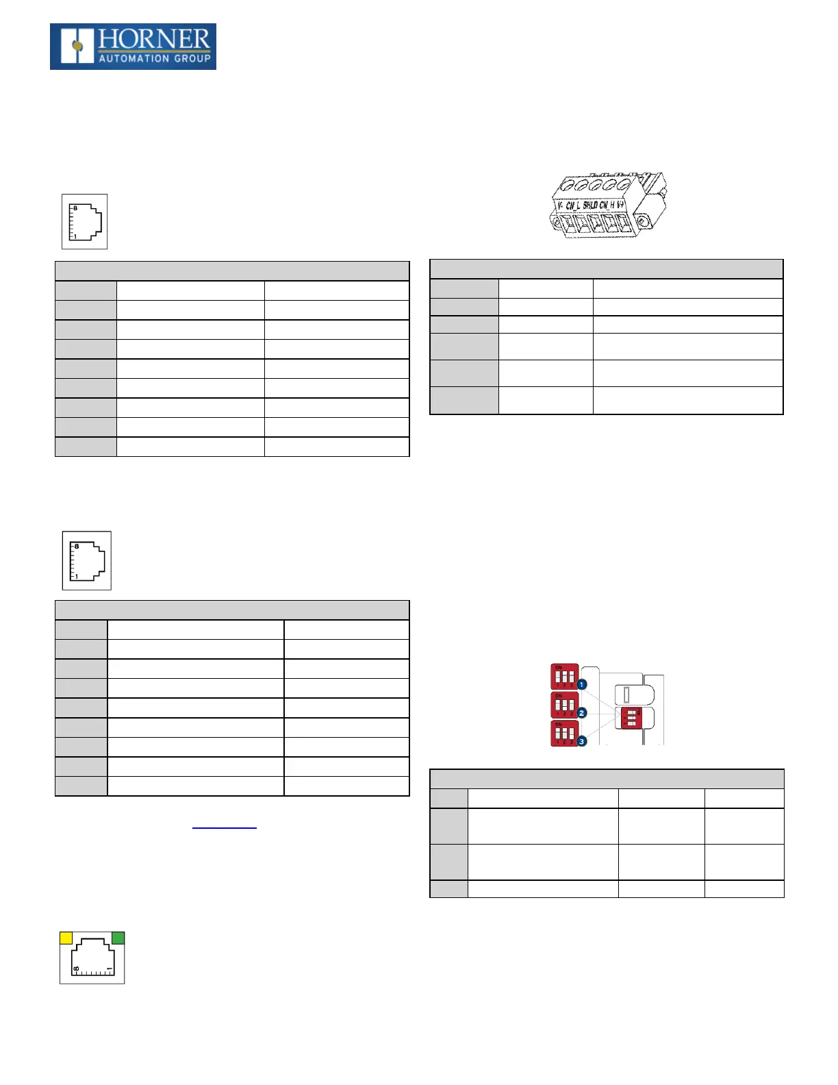
CAN Communications
CAN Pin Assignments
PIN SIGNAL DESCRIPTION
1 V- CAN Ground – Black
2 CN_L CAN Data Low – Blue
3 SHLD Shield Ground – None
4 CN_H CAN Data High – White
5 V+ (NC) No Connect – Red
l
Solid/Stranded Wire: 12-24 awg (2.5-0.2mm).
l
Strip Length: 0.28” (7mm).
l
Locking spring-clamp, two-terminators per con-
ductor.
l
Torque, Terminal Hold-Down Screws: 4.5 – 7 in-
lbs (0.50 – 0.78 N-m).
l
V+ pin is not internally connected, the SHLD pin is
connected to Earth ground via a 1MΩ resistor and 10
nF capacitor.
Dip Switches
DIPSwitches
PIN NAME FUNCTION DEFAULT
1
MJ1 RS-485
Termination
ON = Ter-
minated
OFF
2
MJ2 RS-485
Termination
ON = Ter-
minated
OFF
3 Bootload Always Off OFF
The DIP switches are used to provide a built-in termination
to both the MJ1 port and MJ2 port if needed. The ter-
mination for these ports should only be used if this device is
located at either end of the multidrop/daisy- chained RS-
485 network.

 Loading...

