Page 8
Built-In I/O
The I/O is mapped into OCS Register space, in three sep-
arate areas: Digital/Analog I/O, High-Speed Counter I/O,
and High-speed Output I/O. Digital/Analog I/O location is
fixed starting at 1, but the high-speed counter and high-
speed output references may be mapped to any open
register location .
Digital and Analog I/O Function Registers
Digital Inputs %I1-12
Reserved %I13-31
ESCP Alarm %I32
Digital Outputs %Q1-12
Reserved %Q13-24
Analog Inputs %AI1-2
Reserved %AI3-12
Analog Outputs %AQ9-10
Reserved %AQ1-8
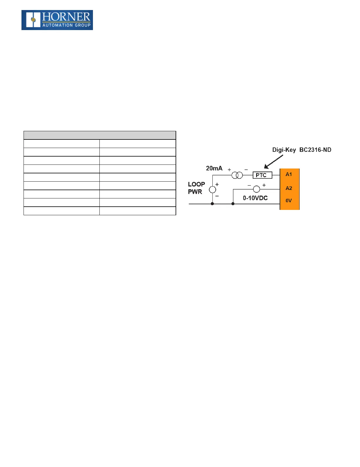
Analog Input Tranzorb Failure
A common cause of Analog Input Tranzorb Failure on Ana-
log Inputs Model 2, 3, 4 & 5: If a 4- 20mA circuit is initially
wired with loop power, but without a load, the analog input
could see 24VDC. This is higher than the rating of the tran-
zorb. This can be solved by NOT connecting loop power
prior to load connection, or by installing a low-cost PTC in
series between the load and analog input.

 Loading...

