Page 3
CONTROLLER OVERVIEW
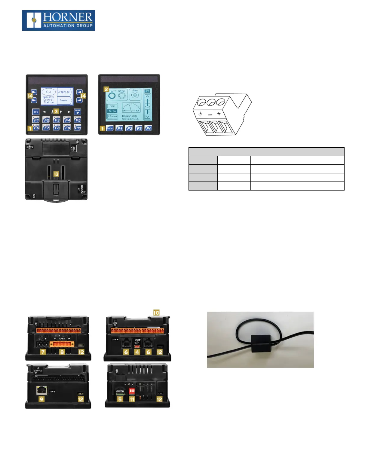
Overview of XLE and XLT
1. Function Keys
2. Touchscreen
3. Navigation Keys
4. USB Mini-B Port
5. High Capacity microSD Slot
6. RS232/RS485 Serial Ports (2)
7. Wide-Range DC Power
8. CAN Port
9. Ethernet LAN Port (XLEe and XLTe only)
10. Optional Built-In I/O (Models 2-6 only)
11. Configuration Switches
12. Mounting Clip Locations
13. DIN Rail Clip
14. Softkeys
NOTE: See Precaution #12 on about USB and grounding.
Power Wiring
NOTE: The Primary Power Range is 10VDC to 30VDC.
Primary Power Port Pins
PIN Signal Description
1 Ground Frame Ground
2 DC- Input Power Supply Ground
3 DC+ Input Power Supply Voltage
DC Input / Frame
l
Solid/Stranded Wire: 12-24 awg (2.5-0.2mm)
l
Strip length: 0.28” (7mm)
l
Torque, Terminal Hold-Down Screws: 4.5 – 7 in-lbs
(0.50 – 0.78 N-m)
l
DC- is internally connected to I/O V-, but is isolated
from CAN V-. A Class 2 power supply must be used.
Power Up
1. OPTION: Attach ferrite core with a minimum of two
turns of the DC+ and DC- signals from the DC supply
that is powering the controllers.
2. Connect to earth ground.
3. Apply recommended power.

 Loading...

