Calibrating (Teach) the sensors
¾ Calibrate the sensor after installation, replace-
ment or a software update.
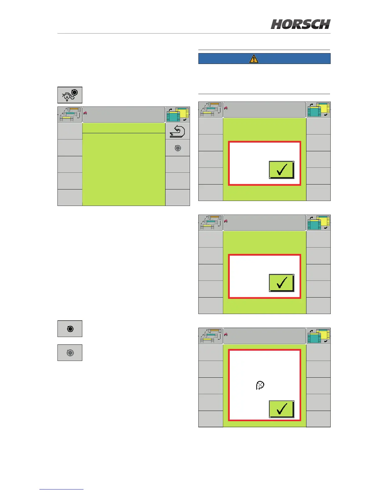
Softkey for accessing the Calibration
page.
CALIBRATION
row 2 : row 14 :
3.55 mA 3.61 mA
4.63 mA 3.60 mA
row 6 : row 16 :
3.76 mA 3.96 mA
3.74 mA 3.57 mA
row 9 : row 19 :
4.01 mA 4.09 mA
4.00 mA 4.27 mA
row 10 : row 23 :
4.10 mA 3.51 mA
3.52 mA 3.52 mA
Calibration
All allocated and active sensors are displayed
on the Calibration page.
The following prerequisites must be met to be
able to perform the calibration:
• No speed signal
• No working signal
• Machine unfolded
• Drill units do not touch the ground
• Value range (without load) in which the sensor
can be calibrated: 2.8 mA - 5.2 mA
The Teach softkey is displayed if all
prerequisites are met.
The Teach softkey is greyed if one of
the prerequisites is not met.
¾ Press the Teach softkey to calibrate.
All sensors are calibrated together.
¾ Check after calibration is completed whether
the current values of the sensors have been
accepted. They are displayed in light grey.
NOTE
Pop-up messages are displayed when the soft-
key Teach is pressed while grey. They indicate
which prerequisites have not yet been met.
Speed > 0
Calibration pop-up 1 - Machine not stopped
Working position
Calibration pop-up 2 - Machine still in working position
Calibration
not possible:
Sensor in row
outside
Value range:
Calibration range
2.80 - 5.20 mA
2
Calibration pop-up 3 - Sensor outside the value range