¾ Slightly lift the machine.
¾ Remove clips from area (1).
¾ Lower the machine.
¾ Reinsert the clips in area (2).
¾ Lower the machine.
¾ Remove clips from area (2).
¾ Lift the machine.
¾ Reinsert the clips again in the area (1).
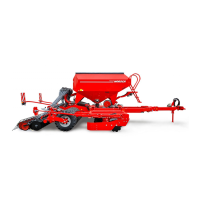
• The frame for the seed bar consists of rec-
tangular hollow tubing. It must be aligned
horizontal in the direction of travel:
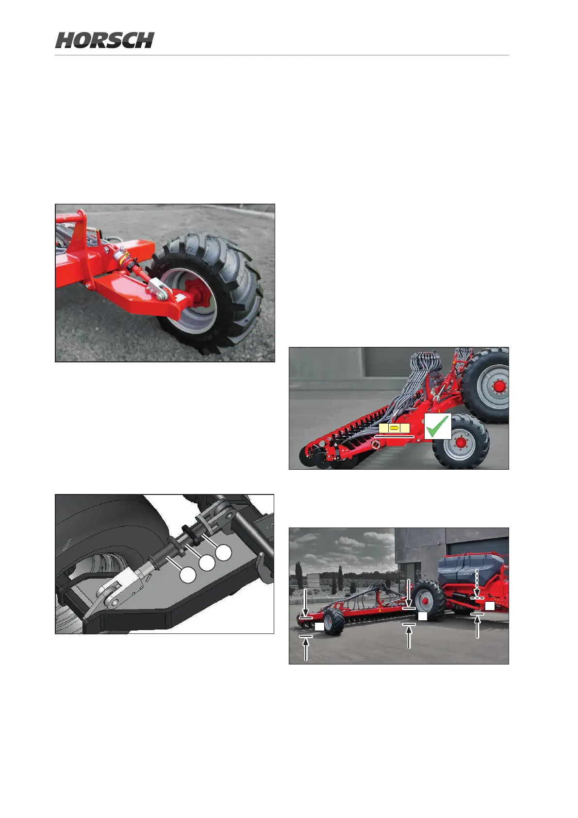
• The height (a) of the frame above the ground
must be the same across the entire machine
width:
a
a
a
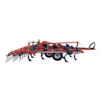
The support wheels stabilise the seed bar and
ensure uniform working depth over the entire
working width.
The support wheels must rest on the ground when
the machine is unfolded and lowered to the work-
ing position.
The aluminium clips are plugged on the setting
bars. The clips may only be removed, respec-
tively inserted when the respective side is
relieved.
It is therefore necessary to lower the machine
or raise it so that the support wheels are loaded
or relieved.
1
2
3
Setting bar with adjustment ranges
¾ Always ll all adjustment areas (1) and (2)
completely with clips, if this is possible.
¾ Insert clips, which are not required, in area (3).
¾ Adjust both support wheels the same.
38
 Loading...