¾ Adapt the height of the support wheels to
the respective ground conditions and tractor
used.
¾ Check the drilling depth over the entire work-
ing width before starting work and, in case of
larger elds, at regular intervals during work!
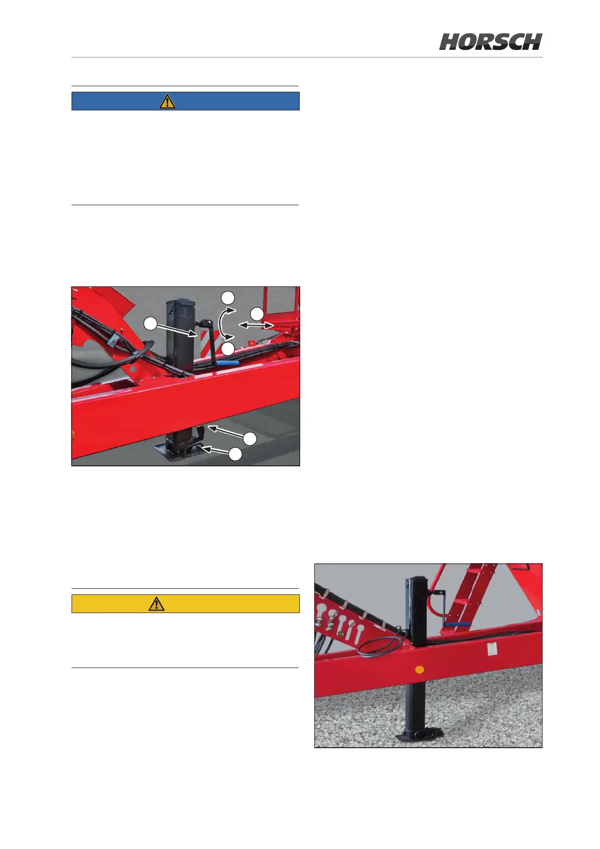
The support’s height can be adjusted via the
crank (a) and the linch pin (b).
Support in transport position
(a) Linch pin
(b) Crank
(c) Gear shifting
(d) Lift
(e) Lower
(f) Handle
Injuries from crank kick-back
¾ Slowly relieve the crank at the end of the
rotary movements.
For quick extension and retraction as well as
bridging ground clearance
¾ Pull out the crank until the gear engages (c).
Slightly turn the crank, if necessary.
¾ The shift lock must engage.
¾ To lift and lower the machine
¾ Push in the crank until the gear engages (c).
Slightly turn the crank, if necessary.
¾ The shift lock must engage.
¾ Engage the load gear and set the height nec-
essary for coupling.
¾ Crank up the support after coupling.
¾ Fold down the crank while the gear is en-
gaged.
¾ Remove the cotter pin on the linch pin (a).
¾ Raise the handle (f), relieve the linch pin and
pull it out.
¾ Guide the base plate on the handle (f) up to
the end position.
¾ Insert the linch pin (a) and secure it with the
cotter pin.
¾ Remove the cotter pin on the linch pin (a).
¾ Raise the handle (f), relieve the linch pin and
pull it out.
¾ Guide the base plate on the handle (f) down
to the end position.
¾ Insert the linch pin (a) and secure it with the
cotter pin.
¾ Engage the rapid or load gear and crank down
the support.
Support in support position
39
Transport position / use in the field
 Loading...