¾ For ne seeds use only the chamfered me-
tering screws. For reasons of dierentiation
these metering screws are marked with an
preceding the size.
Metering screws for ne seeds
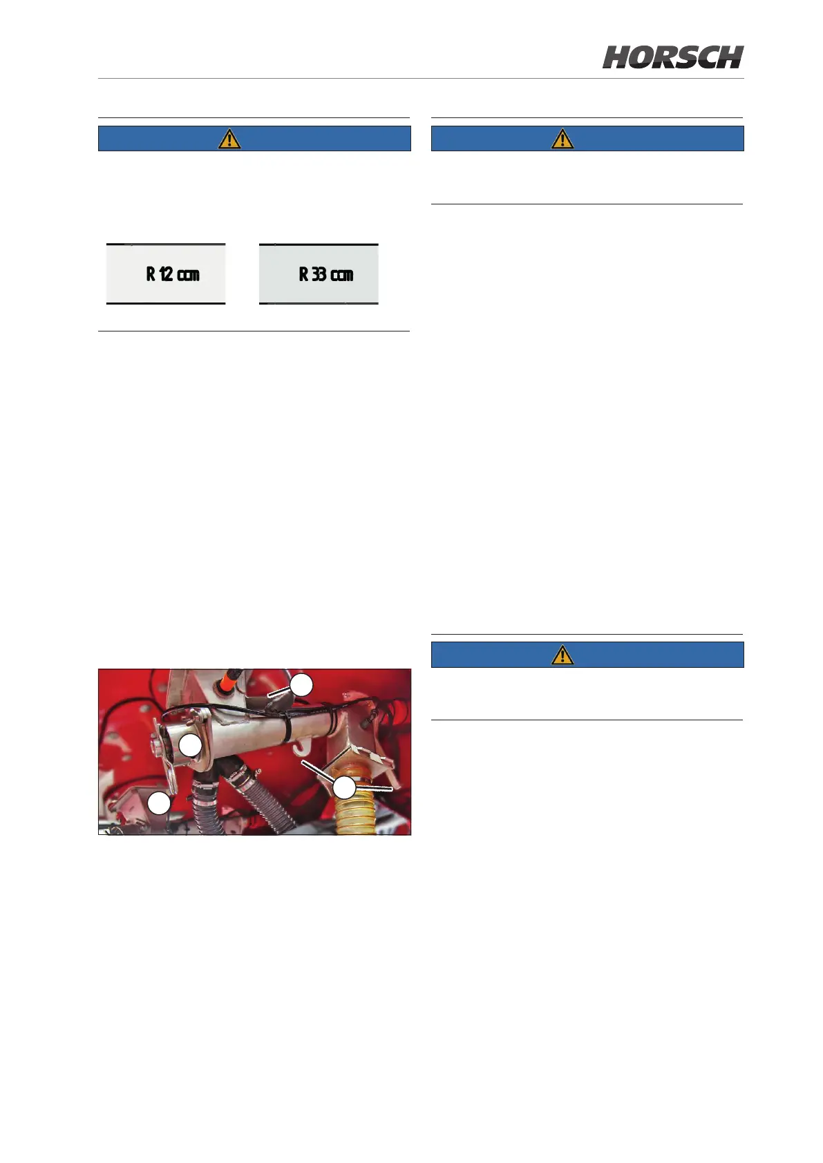
¾ If the hopper is full, loosen the gate valve with
the wing nut and reinsert it into the slot the
other way around (1).
¾ Loosen the two wing nuts on the metering unit
and pull out the lid with the metering screw (2).
¾ Pull the spring pin out of the shaft (3).
¾ Replace the screw. Pay attention to the condi-
tion and correct t of the O-ring on the screw
to be used.
¾ Insert the spring pin.
¾ Reinsert the parts into the metering unit.
¾ Turn the screw further until the hexagon can
be inserted into the drive from the top.
¾ Retighten the wing nuts.
3
2
1
4
The calibration sequence and the input on the
terminal is identical with the calibration for seed/
fertiliser.
¾ Perform calibration with the left metering
screw viewed in travel direction.
¾ Remove the rear hose and attach the calibra-
tion bag (4).
¾ For "low" granulate quantities install the
38 cm³ screw. For high quantities or high
working speed install the 66 cm³ screw.
¾ Fill the hopper with granulate.
¾ Run the metering screw for a moment so that
it is completely lled and calibration will not
be falsied (see E-Manager - lling the
metering cells).
¾ Run the calibration and enter the calibration
weight (see E-Manager instructions).
¾ If the matching speed range is displayed after
entering the weight, you may start drilling.
¾ If the indicated speed range is not suitable for
drilling, you may have to exchange the meter-
ing screw and repeat the calibration process.
The metering units must rst run in during initial use.
¾ During initial use repeat calibration after one
hour running.
62 63
 Loading...