31 of 36
Indesit Company
Service Manual UK English
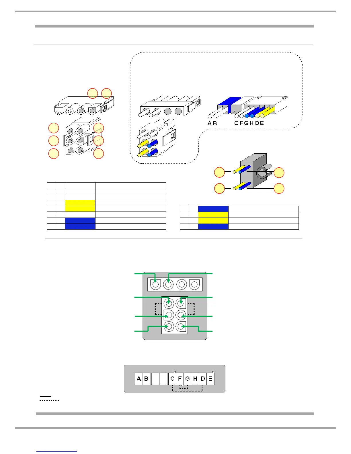
WIRING CONNECTION CHART
A ~ WHITE Freezer Evaporator Fan Motor
B ~ WHITE Freezer Evaporator Fan Motor
C ~ WHITE Evaporator Defrost Heater
D ~ YELLOW Thermal Fuse
E ~ YELLOW Thermal Fuse
F ~ WHITE Evaporator Defrost Heater
G ~ BLUE Thermal Fuse
H ~ BLUE Thermal Fuse
J ~ BLUE To Terminal Block G
K ~ YELLOW To Terminal Block D
L ~ YELLOW To Terminal Block E
M ~ BLUE To Terminal Block H
DEFROST HEATER
AND
THERMAL FUSE
CONNECTION PLUG
(FRONT VIEW – PIN SIDE)
DEFROST HEATER
AND
THERMAL FUSE
CONNECTION PLUG
(REAR VIEW – WIRE SIDE)
ALTERNATIVE
DEFROST HEATER
AND
THERMAL FUSE
CONNECTION PLUG
(REAR VIEW – WIRE SIDE)
THERMAL FUSE
(CLIPPED TO EVAPORATOR)
DEFROST HEATER
AND
THERMAL FUSE
CONNECTION SOCKET
ALTERNATIVE
CONNECTION SOCKET
From ~ Power Module E1 terminal 8
To ~ Freezer Evaporator Fan
From ~ Gutter Heater (foamed in)
To ~ Evaporator Defrost Heater
From ~ Thermal Fuse (internally linked
to socket pin above to Defrost Heater)
From ~ Power Module E1 terminal 6
To ~ Thermal Fuse
From ~ Gutter Heater (foamed in)
To ~ Evaporator Defrost Heater
From ~ Power Module E1 terminal 1
To ~ Freezer Evaporator Fan
From ~ Thermal Fuse (internally linked
to socket pin above to Defrost Heater)
From ~ Power Module E1 terminal 2
To ~ Thermal Fuse
C
D
E
F
G
H
BA
K
L
J
M
A B
F
G
H
C
D
E
KEY
= Indicates Internal Links