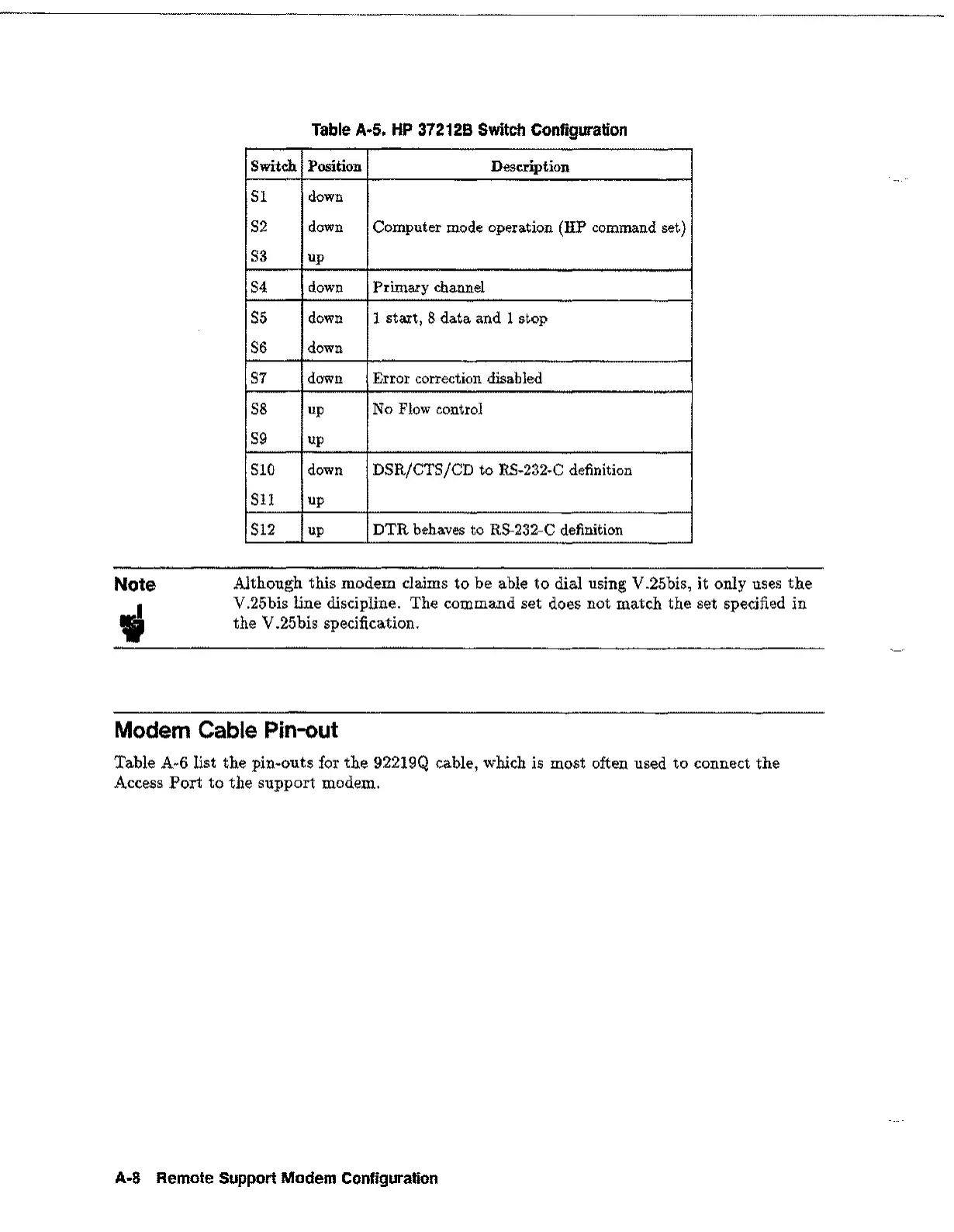
Table A·5. HP 372128 Switch Configuration
Switch
Position
Description
SI down
S2
down
Computer mode operation (HP command set)
S3
up
S4
down Primary channel
S5
down
1 start, 8 data and 1 stop
S6
down
S7
down
Error correction disabled
S8
up
No Flow control
S9
up
SID
down
DSR/CTS/CD to RS-232-C definition
S11
up
S12
up
DTR behaves to RS-232-C definition
Note
Although this modem claims to be able to dial using V.25bis, it only uses the
V.25bis line discipline. The command set does not match the set specified in
the V.25bis specification.
Modem Cable Pin-out
Table A-6 list the pin-outs for the 92219Q cable, which is most often used to connect the
Access Port to the support modem.
A·a
Remote Support Modem Configuration
 Loading...