J
i
h
9
c
D
J
b
1
412A
Input
'
Resistance
Model 4
12A
5-13.
INPUT RESISTANCE
CHECK.
a.
Connect the Model 412A/AR, dc standard and
10
rnegolim resistor
as
shown
in
.Figure
5-1.
b.
Set 412A
FUNCTION
to
VOLTS,
POLARITY to
+.
c. Adjust
412A
RANGE and dc standard output to
voltages listed in Table
5-3.
A
correct meter
reading in each case verifies the input resistance
where:
Ein
=
Eapplied
[
&&]
Table
5-3.
Input Resistance Checks
100
mV
412A
Meter
Reading
(?
1
%)
5.0
mV
22.5
mV
90.9
mV
0.95
V
IOMQ
30
Ma
100
Ma
200
Ma
Section
V
c. Set ac voltmeter FUNCTION
to
AC
VOLTS,
RANGE to
IO
V.
d. Adjust oscillator frequency to
60
Hz,
and adjust
output for an indication
of
7.07
V
on
ac
voltmeter. This corresponds
to
a
IO
V
pcak
;IC
noise signal at the
412A
input.
e. The 412A meter rcadingshould
be
02
I%(l
minor
division
on
upper scale)..
5-15.
ADJUSTMENT AND CALIBRATION
PROCEDURE.
5-16.
The following proccdures should bc pcrfornicd
only
if
it has been determined by the Performance Chccks outlincd
in
Paragraph
5-5
that the Model
412A/AR
docs
not
iiicct
specifications.
5-17.
CABINET REMOVAL.
a. Disconnect power cord from powcr source.
b.
On cabinet model, rcmovc two rctaining
scrcws
near center of rear panel. On rack modcl, rciiiovc
three retaining screws
in
rcar
of
covcr.
c.
Slide instrument chassis forward
out
of
cabinct.
5-18.
MECHANICAL ADJUSTMENT
OF
METER
ZERO.
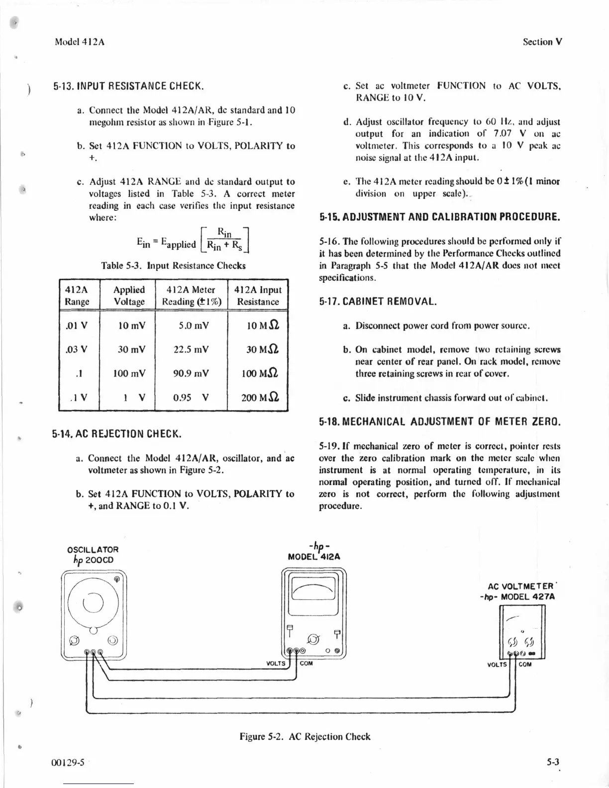
5-14.
AC
REJECTION
CHECK.
5-19.
If
mechanical zero
of
mctcr is corrcct, pointcr rcsts
over the zero calibration mark
on
thc nwtcr scalc wlicii
voltmeter as shown in Figure
5-2.
instrument is at normal opcrating tcmpcraturc,
in
its
normal operating position, and turncd
off.
If
nicclianical
zero is not corrcct, perform thc following adjuslment
procedure.
a.
Connect the Model
412A/AK,
oscillator, and ac
b.
Set 412A FUNCTION to
VOLTS,
POLARITY to
+,
and RANGE to
0.1
V.
-hp-
MODEL
412A
OSCILLATOR
hp
200CD
Figure
5-2.
AC
Rejection Check
001
29-5
5
-3