Model
41 2A
SECTION
IV
THEORY
OF
OPERATION
4-1.
GENERAL.
4-2.
The kp- Model
412AIAR
uses a chopper-stabilized
amplifier circuit to produce a meter indication proportional
to the voltage, current, or resistance being measured.
4-3.
BLOCK
DIAGRAM ANALYSIS.
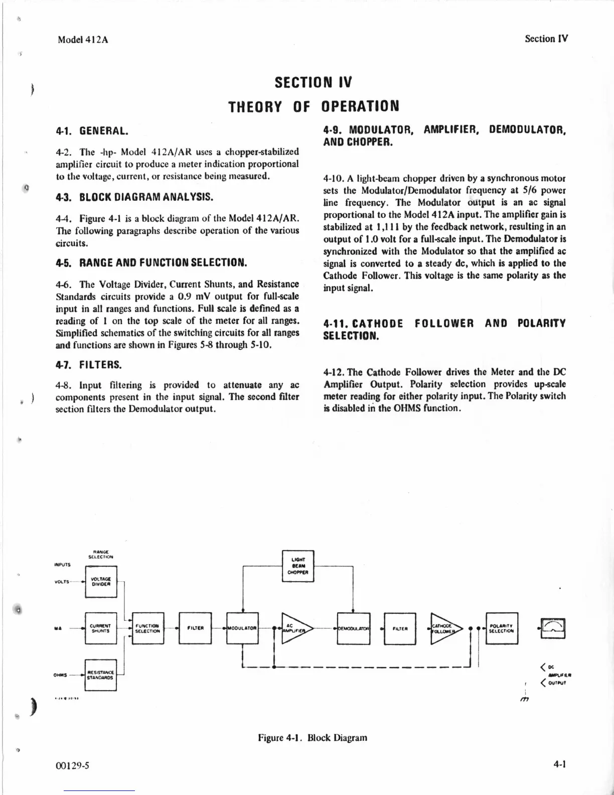
44.
Figure
4-1
is
a block diagram
of
the Model
412AIAR.
The following paragraphs describe operation of the various
circuits.
4.5.
RANGE AND FUNCTION SELECTION.
4-6.
The Voltage Divider. Current Shunts, and Resistance
Standards circuits provide a
0.9
mV output for full-scale
input in all ranges and functions. Full scale
is
defined as a
reading
of
1
on
the top scale of the meter for all ranges.
Simplified schematics
of
the switching circuits
for
all ranges
and
functions are shown in Figures
5-8
through
5-10,
47.
FILTERS.
4-8.
input filtering is provided to attenuate any ac
components present in the input signal. The second fdter
section filters the Demodulator output.
RANOC
SELtCllOW
r
Section
1V
4-9.
MODULATOR, AMPLIFIER, DEMODULATOR,
AN0
CHOPPER.
4-10. A
light-beam chopper driven by a synchronous motor
sets the Modulator/Demodulator frequency at
516
power
line frequency. The Modulator output is an ac signal
proportional
to
the Model
412A
input. The amplifier
gain
is
stabilized at
1
,111
by the feedback network, resulting in an
output
of
1
.O
volt for a full-scale input. The Demodulator
is
synchronized with the Modulator
so
that the amplified ac
signal
is
converted to
a
steady dc, which
is
applied
to
the
Cathode Follower. This voltage is the same polarity as the
input signal.
4-11.
CATHODE FOLLOWER AND POLARITY
SELECTION.
4-12.The Cathode Follower drives the Meter and the
DC
Amplifier Output. Polarity selection provides upscale
meter reading for either polarity input. The Polarity switch
is disabled in the
OHMS
function.
I
Figure
4-1.
Block Diagram
00
129-5
4-1