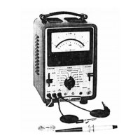
Model
4
12A
a. Turn 412A ON and allow a 20-minute warm-up
period. This
allows
meter movement
to
reach
normal operating tcniperaturc.
b. Turn instrumcnt OFF and allow
30
seconds for all
capacitors
to
discharge.
c.
Rotate mechanical zero-adjustment screw
clockwise until meter pointer is to left of zero and
moving upscale toward zero.
d. Continue to rotate adjustment screw clockwise
and stop when pointer
is
exactly over zero mark.
If pointer overshoots zero, repeat steps
c
and d.
e. With pointer exactly on zero, rotate adjustment
screw counterclockwise approximately
10
degrees.
This frees adjustment screw from meter
suspension. If pointer moves during this step,
repeat steps
c
through e.
5-20.
HUM BALANCE ADJUSTMENT.
a. Turn
412A
ON and allow 5-minute warm-up
period.
b.
Set FUNCTION
to
VOLTS.
c.
Connect oscilloscope to
DC
AMPLIFIER
OUTPUT.
d. Adjust HUM BAL (R126, Figure
5-3)
for
minimum
10
Hz
signal
on
oscilloscope. (If power
line frequency is
50
Hz, beat frequency will be
8-1/3
Hz instead of
10
Hz.)
NOTE
The Hum
Bal.
control docs not affect
the 120
Hz
ripple. Adjust only for
minimum 10
Iiz
(or
8-1/3
Hz) signal.
With the VOLTS lead shorted
to
COM
lead and POLARITY set
to
t,
the 412A meter will show a
minimum deflection when the Hum
Bal.
is
correctly adjusted.
5-21.
CATHODE FOLLOWER BIAS ADJUSTMENT.
a.
Set
412A
RANGE
switch fully clockwise (one step
beyond 1000).
b. Adjust rear panel BIAS
ADJ
(R116)
to
set
meter
pointer approximately on zero. This adjustment is
not critical, since
any
deviation from zero is
reduced more
than
100
times when the RANGE
switch is in any operating position.
00
129-5
Section
V
5-22.
METER ELECTRICAL ZERO ADJUSTMENT.
NOTE
Meter electrical zero adjust circuit
may not
be
installed in 412A cabinet
model instruments with serial
number 424-14482 and below, or
in
41
2AR rack mount instruments with
serial number 424-1 5082 and below.
a. Turn 412A ON and allow
a
30-minute warm-up
period.
b. Set FUNCTION
to
VOLTS, RANGE
to
.001.
c.
Short VOLTS probe
to
COM lead.
d. Adjust ZERO ADJ (R129) for zero dcflcction of
the meter pointer. Check the zcro adjustmcnt by
switching POLARITY from
t
to
-
When zero
is
adjusted properly, this action should produce a
minimum amount of deflection.
5-23.
AMPLIFIER
GAIN
ADJUSTMENT AND METER
CALI
B
R
AT1
0
N
.
a.
A
dc standard and
a
de voltmeter arc rcquircd for
these adjustments.
b.
Connect
4
12A VOLTS probe and COM lcad
to
dc
standard output.
Set
FUNCTION
to
VOLTS,
RANGE
to
1
V,
POLARITY to
t.
c.
Connect dc voltmeter betwccn dc standard output
(t)
and 412A
DC
AMPLIFIER OUTPUT liigli.
d.
Set
dc standard output to
+I
V.
e.
Adjust 412A GAIN
CAL
(RI
19)
for zcro
indication on test voltmctcr.
A
10
mV rcading
on
test voltmcter indicates
1%
crror in
4
12A gain
calibration.
f. Adjust METER CAL (R46) to sct 412A meter
pointer on
1.0
on top scale. Disconnect test
voltmctcr.
g.
Chcck 4l2A calibration at full scalc on all ranges
as outlined
in
Paragraph
5-10.
If
any rcading
is
in
error morc than
I%,
rcadjusl
GAIN
CAL
(It1
19)
to
bring
all
readings within
f
1
X.
5-24.
OHMMETER ADJUSTMENT.
a. Set 412A FUNCTION to OIIMS, ItANGIi to
XI
K.
Make ccrtain
MA/OlIMS
and (:OM
lcads
are not
connected through wmc cxtcrnal rcsistancc.
5-5

 Loading...