hlodcl4
12A
SECTION
111
0
PER
AT1
N
G
3-1.
INTRODUCTION.
3-2.
The
-lip-
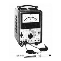
Model 412A/AR
DC
Vacuum Tube
Voltmeter nieasures dc voltages from
1.0
mV full scale to
lo00 V
full
scale with
an
accuracy of
1%
of
full
scale.
Current measurement ranges are from
0.001
mA
full
scale
to
1000
mA
full
scale, with accuracy
of
2%
of
full scale.
The Model
41
2A/AR makcs resistaricc measurements from
1.0
ohm center
scale
to
100
megohms center scale.
Resistance measurenicnt accuracy is
5%
of
reading between
.3
and
3
on
the ohms scale.
A
dc amplifier output is also
provided.
Voltage
gain of tlic amplificr is from
-1000
to
+1000,
depending
on
range selcctcd. Amplifier output is
1
.O
V
at full scale. and maxinium current load is
1
.O
mA.
3-3.
LOW-LEVEL ELECTRICAL PHENOMENA.
34.
Stray low-level electrical phenomena may cause error
in
low voltage measurements. When using the lower voltages
of the Model 412A, consider the possibility
of
low-level
voltages produced by thermoelectric effects, residual
charges on capacitors, battery action,
or
flexing
of
coaxial
cables,
3-5.
The voltagc probe, currentlresistance lead, and
common lead
of
the Model 412A/AR are all designed to
have a very low thermoelectric effect with copper, the most
commonly used conductor. However, some component
leads such as transistors and reed relays may have leads
made
of
such alloys as nickel-iron, which produce a
thermoelectric voltage when joined with copper. Whenever
possiblc, connect tlic
412A
leads to copper. If this
is
not
possible, the voltage probe and common lead should both
In:
conncctcd
to
the
smic
kind
of
inctal compncnt lead,
and both connection points maintained at the same
tc
111
pcra
t
urc.
34.
To minimize tlic possibility
of
battery action when
making
low
voltage mcasurcments, make sure the 412A
probe tip and common lcad alligator clip are clean.
Also
be
surc
tlic component leads or other points of connection are
clean. The prcsence
of
sonic chemicals such
as
solder flux
niay cause noticeable nieasiirement error due to battery
action.
NOTE
Operating the Model 412A/AR without
grounding the third (power line ground)
wire
of
the power cable will result in a
zero offset
of
the meter and oscillation
of
the pointer.
IN
STRU
CTiO
NS
3-7.
TURN-ON PROCEDURE.
Section
111
BEFORE CONNECTING PRIMARY
POWER, MAKE SURE THE REAR
PANEL 115/230 V SLIDE SWITCH
IS
SET
TO
THE POWER LlNE
VOLTAGE
TO
BE
USED.
INCORRECT SETTING MAY
RESULT IN DAMAGE TO THE
INSTRUMENT.
a. Make sure the proper fuse is installed for operation
with the power line voltage to be used. A
0.6
A
slow-blow fuse should be used for
I
IS
V
operation, and a
0.4
A slow-blow fuse for
230
V
operation.
b. Connect
to
ac power and turn instrument ON.
Allow
a
S-minute warm-up period.
3-8.
VOLTAGE
MEASUREMENT.
a.
Set
FUNCTION switch to VOLTS, and select
proper polarity.
b. Set RANGE switch to desired range.
If
in doubt,
set
switch to high range and downrange as
necessary.
c.
Connect VOLTS and
COM
leads across circuit
or
component, and read voltage.
DO
NOT OVEKLOAD THE
INSTRUMENT. MOMENTARY
OVERLOADS UP TO TEN TIMES
FULL SCALE WILL NOT DAMAGE
THE INSTRUMENT; HOWEVER,
CURRENT SHUNTS, AND
INTERNAL RESISTANCE
STANDARDS ARE NOT
PROTECTED FROM EXTREME
OVERLOAD.
33.
CURRENT MEASUREMENT.
a. Set FUNCTION switch to
MA.
b.
Set RANGE switch to desired range.
If
in doubt,
select high range and downrange as necessary.
00
1
29-5
3-1

 Loading...