Model
4
12A
h. Turn 412A ON and allow 30-second warm-up
period. Observe de voltage amplitude on
oscilloscope.
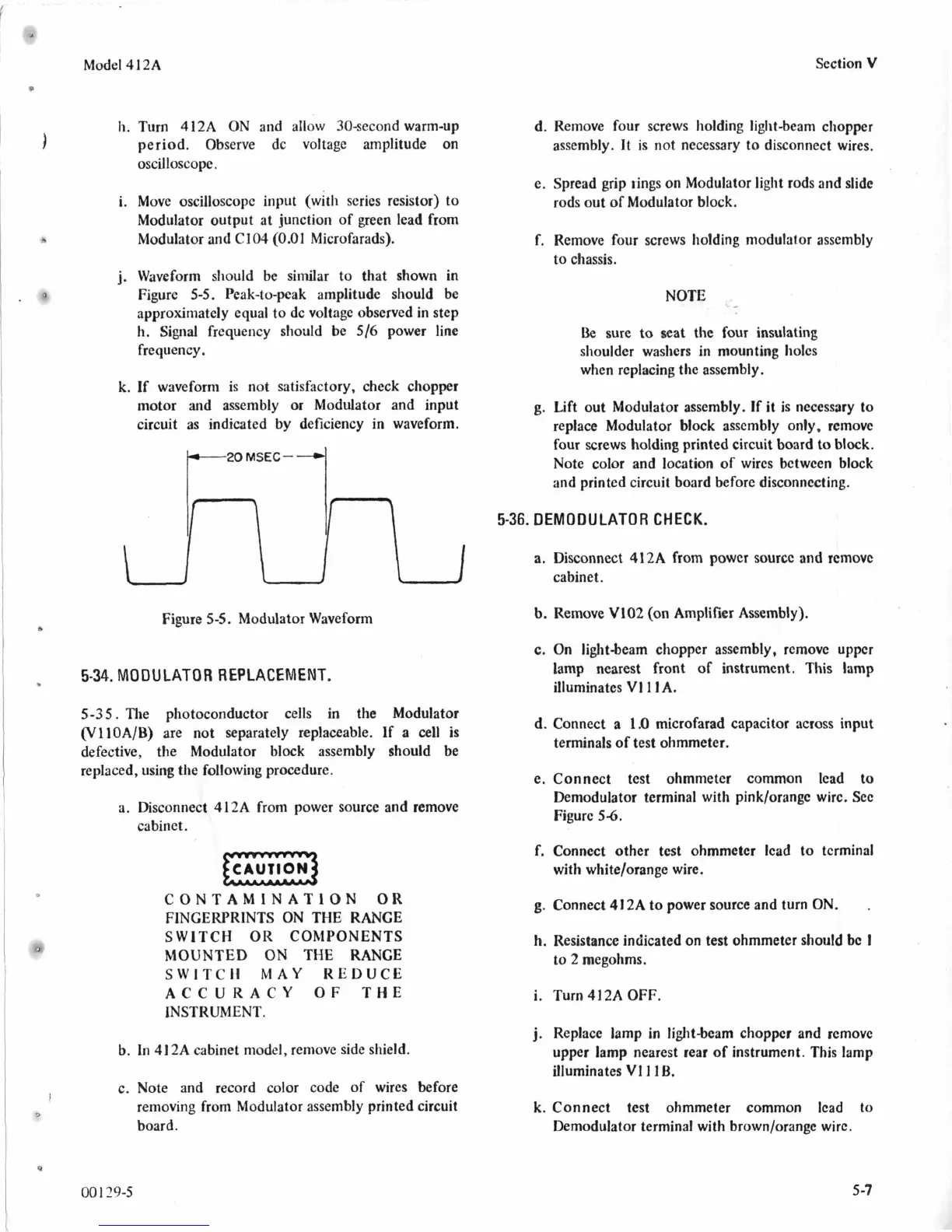
i. Move oscilloscopc input (with series resistor) to
Modulator output at junction of green lead from
Modulator and C104
(0.01
Microfarads).
j.
Waveform should be similar
to
that shown in
Figure
5-5.
Peak-to-peak amplitude should be
approximately equal
to
dc voltage observed in step
h. Signal frequency sliould be
5/6
power line
frequency.
k. If waveform is not satisfactory, check chopper
motor and assembly or Modulator and input
circuit as indicated by deficiency in waveform.
p-20
MSEC-
--)1
Figure
55.
Modulator Waveform
5-34.
MODULATOR
REPLACEMENT.
5-35.
The photoconductor cells in the Modulator
(VllOA/B) are not separately replaceable.
If
a
cell
is
defective, the Modulator block assembly should be
replaced, using the following procedure.
a. Disconnect 412A from power source and remove
cabinet.
CONTAMlNATION OR
FINGERPRINTS
ON
THE RANGE
SWITCH OR COMPONENTS
MOUNTED
ON
THE RANGE
SWlTCII MAY KEDUCE
ACCURACY
OF
THE
INSTRUMENT.
b.
In 41 2A cabinet model, remove side shield.
c.
Note and record color code of wires before
removing from Modulator assembly printed circuit
board.
001
29-5
Section
V
d. Remove four screws holding light-beam chopper
assembly. It is not necessary to disconnect wires.
e. Spread grip rings on Modulator light rods and slide
rods out
of
Modulator block.
f. Remove four screws holding modulator assembly
to
chassis.
NOTE
Be
sure
to
seat the four insulating
shoulder washers in mounting holcs
when replacing the assembly.
g.
Lift out Modulator assembly. If it is necessary to
replace Modulator block asscmbly only, rcmovc
four screws holding printed circuit board
to
block.
Note color and location
of
wircs between block
and printed circuit board before disconnccting.
5-36.
DEMODULATOR
CHECK.
a.
Disconnect 412A from powcr sourcc and removc
cabinet.
b. Remove V102 (on Amplifier Assembly).
c.
On
iight-beam chopper assembly, rcmove uppcr
lamp nearest front of instrument. This
lamp
illuminates
VI
1
I
A.
d. Connect a
1.0
microfarad capacitor across input
terminals of test ohmmeter.
e. Connect test ohmmeter common lead
to
Demodulator terminal with pinklorange wirc.
Sec
Figure
56.
f. Connect other
test
ohmmeter lcad to tcrminal
with whitelorange wire.
g.
Connect 412A
to
power source and turn
ON.
.
h. Resistance indicated on
test
ohmmeter
should
bc
I
to 2 megohms.
i. Turn
41
2A
OFF.
j.
Replace lamp in light-beam chopper and remove
upper lamp nearest rear of instrument. This lamp
illuminates
VI
I
1
B.
k. Connect test ohmmeter common lcad to
Demodulator terminal with brownlorange wirc.
5
-7