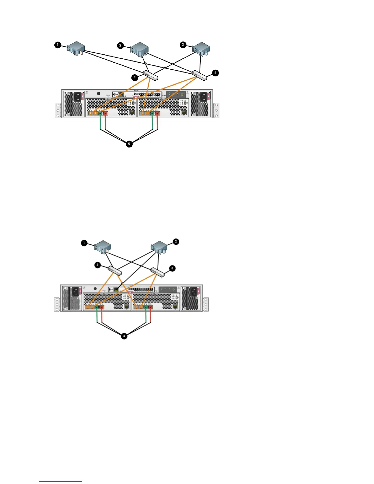
Figure 26 Cabling the controller to front end component—Fibre Channel to switch detail view with
server-based management
1. File server
2. Management server
3. Database server
4. Fiber channel switch
5. LED status indicators for cabling connections to disk enclosures. See Figure 24 (page 36) and Figure 25 (page 37)
for cabling connections.
Figure 27 Cabling the controller to front end components—Fibre Channel to switch detail view with
array-based management
1. File server
2. Database server
3. Fiber channel switch
4. LED status indicators for cabling connections to disk enclosures. See Figure 24 (page 36) and Figure 25 (page 37)
for cabling connections.
38 EVA4400 cabling diagrams
 Loading...