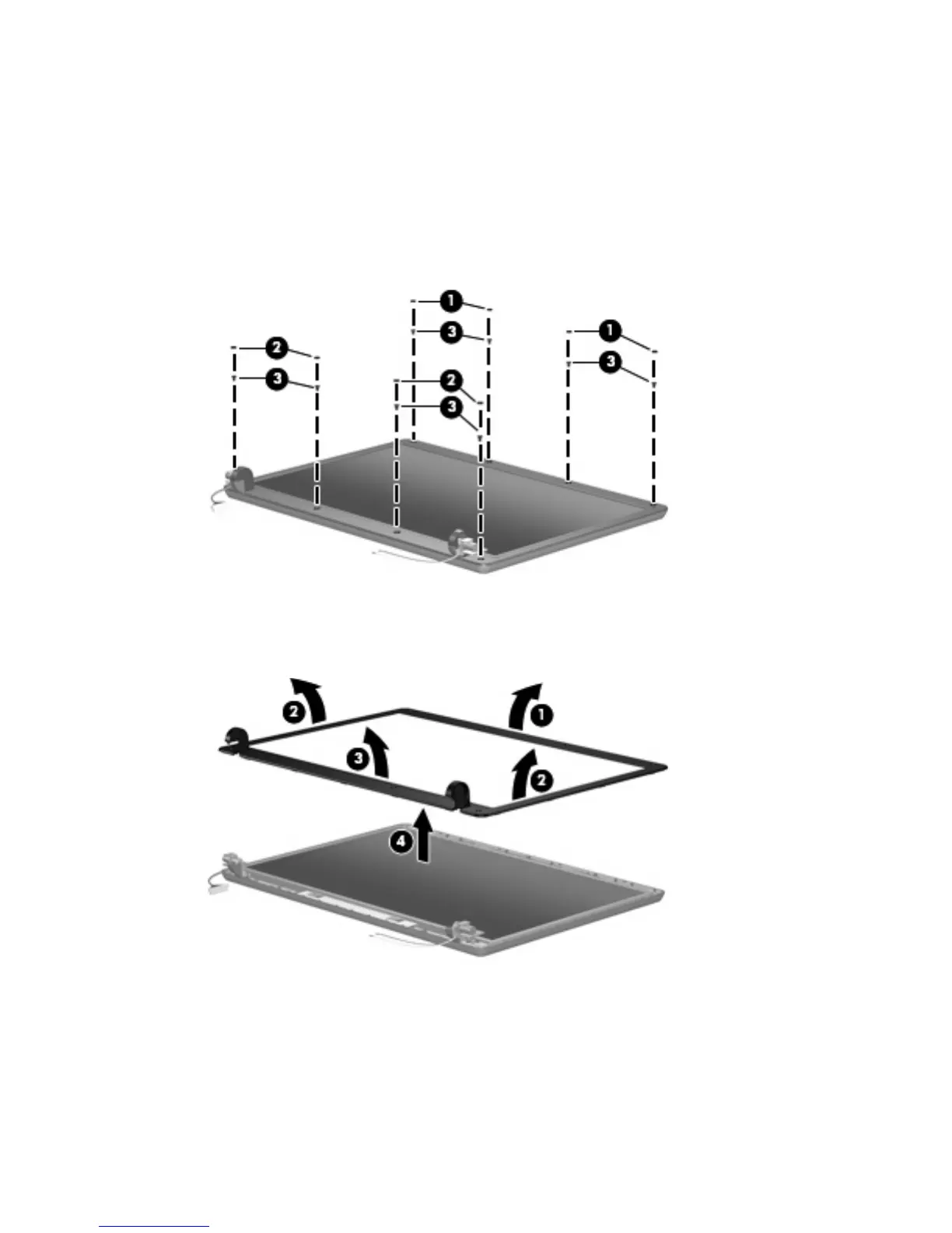
9.
If it is necessary to replace the display bezel or any of the display assembly internal subcomponents,
remove the following display bezel screw covers and screws:
(1) Four round rubber screw covers on the top edge of the display bezel. The display bezel screw
covers and all screws used to secure display assembly internal subcomponents are available in the
Display Screw Kit, spare part number 404714-001.
(2) Four flat rubber screw covers on the bottom edge of the display bezel.
(3) Eight Phillips PM2.5×6.0 screws.
10. Flex the inside edges of the top side (1), the left and right sides (2), and then the bottom side (3) of
the display bezel until the bezel disengages from the display assembly.
11. Remove the display bezel (4). The bezel is available using spare part number 440706-001.
12. If it is necessary to replace the display inverter, disconnect the display panel cable (1) and the
backlight cable (2) from the inverter.
Component replacement procedures 49
 Loading...