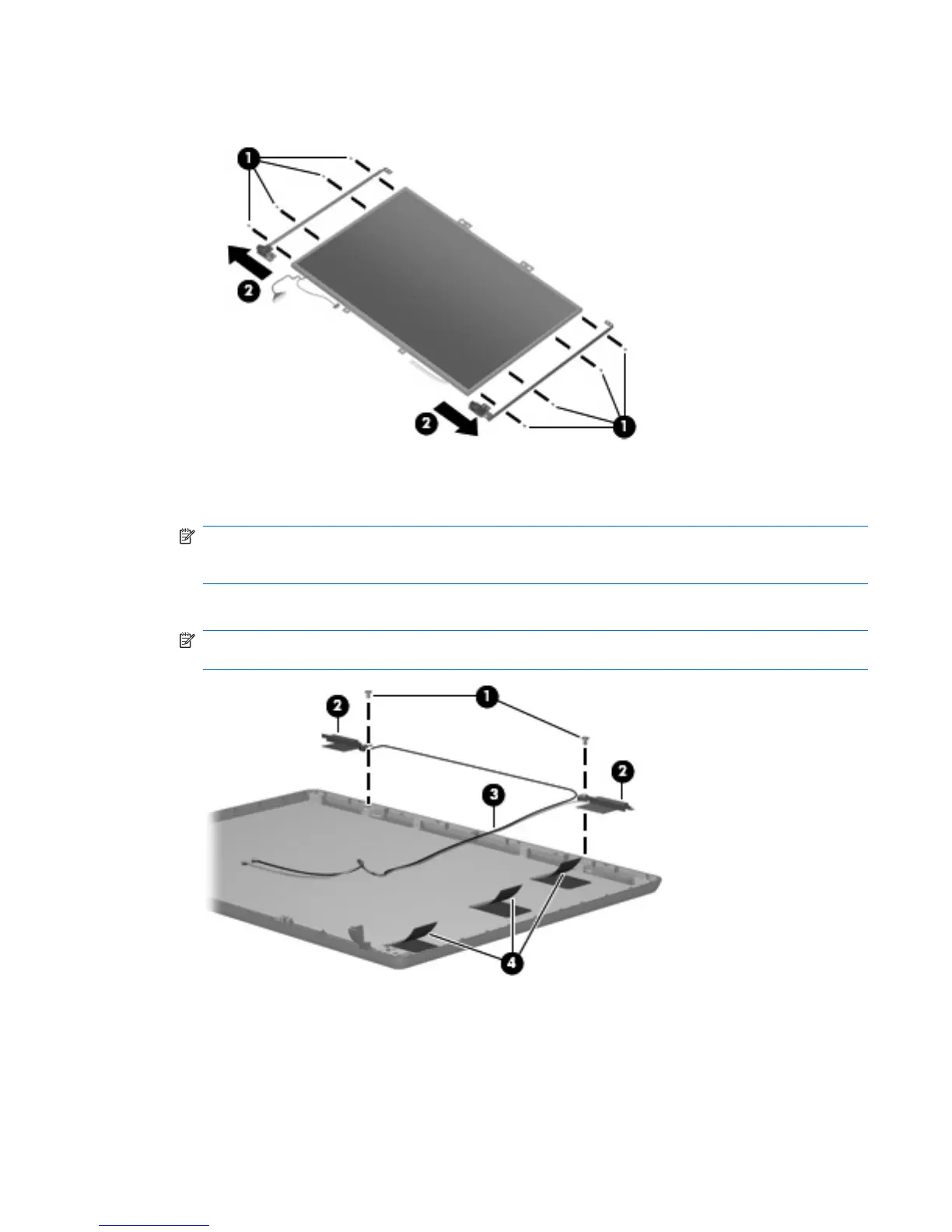
17. Remove the display hinges (2). The hinges are available in the Display Bracket/Hinge Kit, spare
part number 440707-001.
18.
If it is necessary to replace the wireless antenna transceivers, remove the Phillips PM2.5×4.0
screws (1) that secure each transceiver (2) to the display enclosure. The wireless antenna transceivers
and cables are available in the Wireless Antenna Kit, spare part number 441639-001.
NOTE: The wireless antenna transceivers are also attached to the display enclosure with a thin
layer of adhesive. It may be necessary to use a flat-bladed tool to pry the transceivers away from the
display enclosure.
19. Remove the wireless antenna transceivers (2) and cables (3) from the display enclosure.
NOTE: The wireless antenna cables are attached to the display enclosure by a series of pliable
tabs (4) built into the enclosure shielding. Lift the tabs to release the cables.
Reverse this procedure to reassemble and install the display assembly.
Component replacement procedures 51

 Loading...