Model 5328A
Operation
*f. START CLOCK. A "phantomJ' function located
1
switch position clockwise from STOP.
Totalizes the internal
10
MHz clock +N where
N
is
selected by the RESOLUTION switch
(N110).
The scaled output (i.e.,
10
MHz
tN)
is
available at theTime Base Out rear panel
connector.
*g.
DVM/A. A "phantom" function located 2 switch positions clockwise from STOP. Used
for scaling DVM measurements. Counter displays
DVM/freq. A where freq A
(10
MHz.
N selects the number of events at A over which the measurement
is
made.
*h. DVM, A--B. A "~hantom" function located 3 switch ~ositions clockwise from STOP
The voltage at the DVM terminals
is
integrated over'the synchronized time interval
defined by events at channels Aand B. Unitsof the displayed reading arevolt@seconds.
FREQ A. Sets counter to measure frequency at channel A.
PER A. Sets counter to measure period at channel A.
PER AVG A. Sets counter to make a period average measurement of the signal at
channel
A. The number of periods over which the average measurement
is
made
is
determined
by
N,
selected by the RESOLUTION switch.
RATIO B/A. Sets counter to measure the ratio of the frequency at channel B to the
frequency at channel A.
T.I.
A--B. Sets counter to make
a
time interval measurement. Start signal
is
applied to
channel A and the stop signal is applied to channel
B.
T.I. AVG A-B. Sets counter to make a time interval average measurement of the time
interval from A to
B.
The number of time intervals over which the average measurement
is
made
is
determined by
N,
selected by the RESOLUTION switch.
EVENTS
C,
A+B. Sets the counter to totalize the number of eventsat thechannel
C
input
during the synchronized time interval determined by inputs to channels A and B.
*"phantom" functions which, due to relatively limited use, are not labeled on the 5328A front
panel.
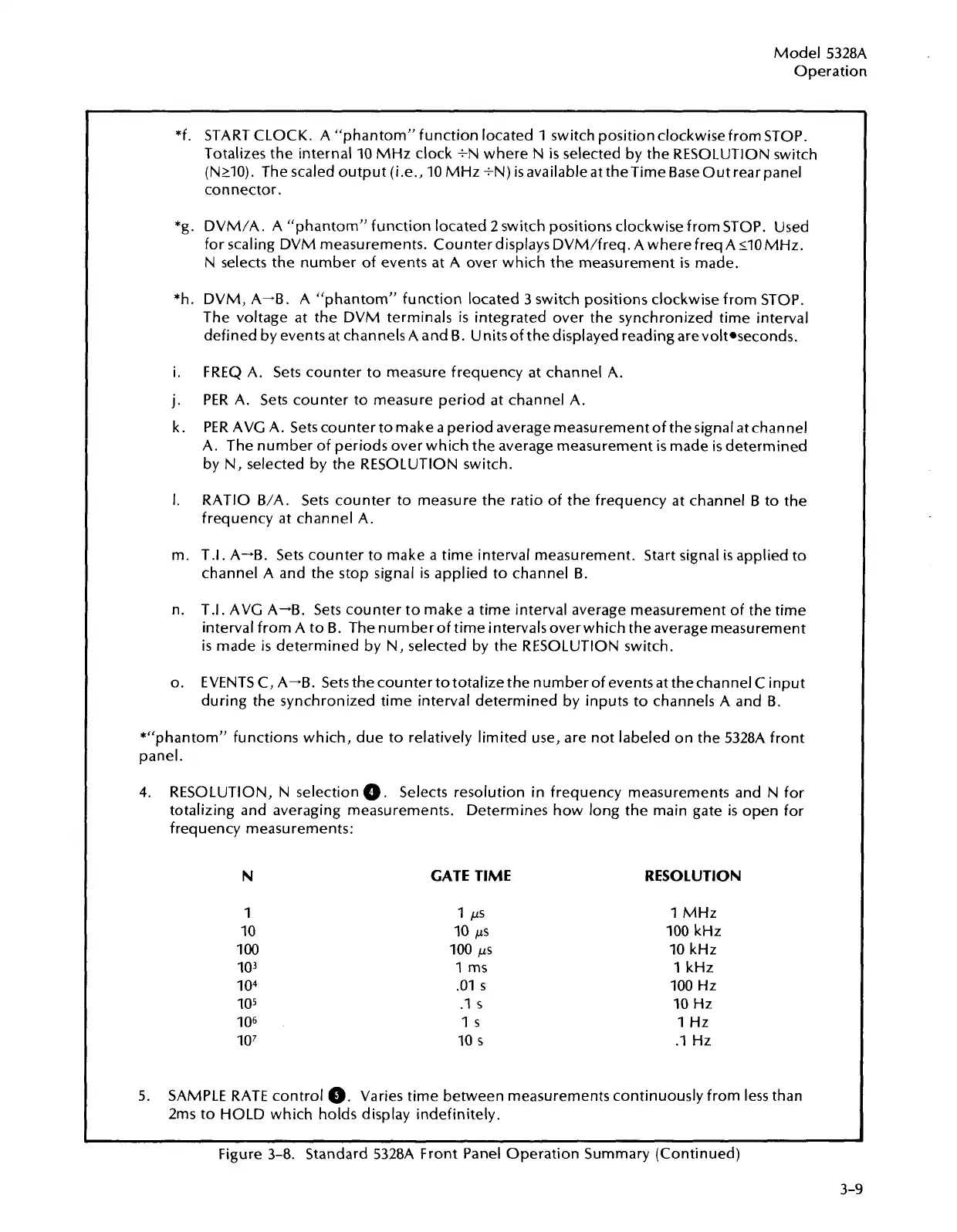
4.
RESOLUTION, N selection
0.
Selects resolution in frequency measurements and
N
for
totalizing and averaging measurements. Determines how long the main gate
is
open for
frequency measurements:
GATE TIME
1
PS
10
ps
100
ps
1
ms
.O1
s
.I
s
I
s
10
s
RESOLUTION
1
MHz
100
kHz
10
kHz
1
kHz
100
Hz
10
Hz
1
Hz
.I
Hz
5.
SAMPLE RATE control
@.
Varies time between measurements continuously from less than
2ms to HOLD which holds display indefinitely.
Figure 3-8. Standard 5328A Front Panel Operation Summary (Continued)
Artisan Technology Group - Quality Instrumentation ... Guaranteed | (888) 88-SOURCE | www.artisantg.com