SVC 4-39
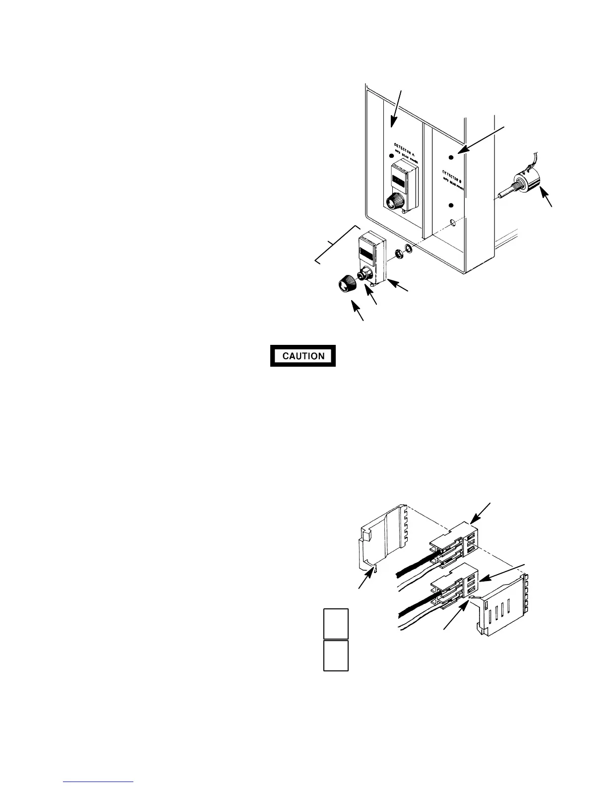
7. Remove the control knob from the potentiome-
ter assembly by pulling it straight off.
8. Using a 1.0-mm hex wrench, loosen the two hex
screws located around the outside of the brass collar.
9. Slide the dial indicator off the shaft of the potentiometer
assembly.
10. Remove the mounting nut securing the
potentiometer assembly.
11. Remove the potentiometer assembly from the
rear of the panel.
12. Remove the interlocking side covers
from the plug using the side edge of
an AMP pin extraction/lance tool
(Part No. 8710-1542).
13. Orient the connector associated with
the new potentiometer assembly in the
same position as the one just removed.
` NPD power control plugs installed in the wrong position will permanently
damage the NPD detector PCB.
` The following steps require protection against ESD (Electro-Static Discharge).
Use a grounded wrist strap (part no. 9300-0969- large, or 9300-0970 - small)
connected to a suitable ground. Failure to heed this caution may result in
damage to the instrument.
14. Install the interlocking side covers on the two connectors which make up the connector to be
installed in the NPD detector PCB.
15. Insert the plug into its connector on the NPD
detector PCB.
16. Remove the 1/2-inch nut from the new poten-
tiometer assembly.
17. Install the new potentiometer assembly on the
panel from the rear.
18. Install the mounting nut and tighten it firmly.
19. Turn the potentiometer shaft fully counterclock-
wise.
20. Slide the dial indicator onto the power control
shaft.
21. While holding the potentiometer shaft fully counter clockwise with a screwdriver, adjust the dial
indicator to read “000”.
NPD DETECTOR B PANEL
POTENTIOMETER
ASSY
TURNS DIAL
NPD DETECTOR
A PANEL
CONTROL KNOB
BRASS COLLAR
DIAL INDICATOR
TO NPD TRANSFORMER
TOP PART OF CONNECTOR
TO NPD BEAD
POWER
CONTROL
BOTTOM PART
OF
CONNECTOR
LOCKING TAB
LOCKING TAB
NOTE
ASSEMBLED
CONNECTORS
5
1
5
1
Artisan Scientific - Quality Instrumentation ... Guaranteed | (888) 88-SOURCE | www.artisan-scientific.com

 Loading...


